Product Description
Custom CNC Turning Machining Spline Shaft Couplings Steering Shaft Coupler Oldham Coupling
Product Description
Coupling refers to a device that connects 2 shafts or shafts and rotating parts, rotates together during the transmission of motion and power, and does not disengage under normal conditions. Sometimes it is also used
as a safety device to prevent the connected parts from bearing excessive load, which plays the role of overload protection.
Couplings can be divided into rigid couplings and flexible couplings. Rigid couplings do not have buffering property and the ability to compensate the relative displacement of 2 axes. It is required that the 2 axes be strictly aligned. However, such couplings are simple in structure, low in manufacturing cost, convenient in assembly and disassembly, and maintenance, which can ensure that the 2 axes are relatively neutral, have large transmission torque, and are widely used. Commonly used are flange coupling, sleeve coupling and jacket coupling.
Flexible coupling can also be divided into flexible coupling without elastic element and flexible coupling with elastic element. The former type only has the ability to compensate the relative displacement of 2 axes, but cannot cushion and reduce vibration. Common types include slider coupling, gear coupling, universal coupling and chain coupling; The latter type contains elastic elements. In addition to the ability to compensate the relative displacement of 2 axes, it also has the functions of buffering and vibration reduction.
Our leading mainly including universal couplings, drum gear couplings, elastic couplings etc.
Main production equipments:
Large lathe, surface grinder, milling machine, spline milling machine, horizontal broaching machine, gear hobbing machine, shaper, slotting machine, bench drilling machine, radial drilling machine, boring machine, band sawing machine, horizontal lathe, end milling machine, crankshaft grinder, CNC milling machine, etc.
| Product Name | Custom CNC Turning Machining Spline Shaft Couplings Steering Shaft Coupler Oldham Coupling |
| Place of Origin | China |
| Certificates | SGS, ISO9001:2008 |
Coupling performance
1) Mobility. The movability of the coupling refers to the ability to compensate the relative displacement of 2 rotating components. Factors such as manufacturing and installation errors between connected components, temperature changes during operation and deformation under load all put CHINAMFG requirements for mobility. The movable performance compensates or alleviates the additional load between shafts, bearings, couplings and other components caused by the relative displacement between rotating components.
(2) Buffering. For the occasions where the load is often started or the working load changes, the coupling shall be equipped with elastic elements that play the role of cushioning and vibration reduction to protect the prime mover and the working machine from little or no damage.
(3) Safe, reliable, with sufficient strength and service life.
(4) Simple structure, easy to assemble, disassemble and maintain.
Inspection equipment:
Dynamic balance tester, high-speed intelligent carbon and sulfur analyzer, Blochon optical hardness tester, Leeb hardness tester, magnetic yoke flaw detector etc.
It is widely used in metallurgical steel rolling, wind power, hydropower, mining, engineering machinery, petrochemical, lifting, paper making, rubber, rail transit, shipbuilding and marine engineering and other industries.
How to select the appropriate coupling type
The following items should be considered when selecting the coupling type.
1. The size and nature of the required transmission torque, the requirements for buffering and damping functions, and whether resonance may occur.
2. The relative displacement of the axes of the 2 shafts is caused by manufacturing and assembly errors, shaft load and thermal expansion deformation, and relative movement between components.
3. Permissible overall dimensions and installation methods, and necessary operating space for assembly, adjustment and maintenance. For large couplings, they should be able to be disassembled without axial movement of the shaft.
In addition, the working environment, service life, lubrication, sealing, economy and other conditions should also be considered, and a suitable coupling type should be selected by referring to the characteristics of various couplings.
If you cannot determine the type, you can contact our professional engineer.
FAQ
Q: Why choose Shengao product?
A: We have our own factory, therefore, we can surely promise the quality of product and provide
you competitive price.
Q: Do you provide OEM Service?
A: Yes, we provide OEM Service.
Q: Do you provide customized machining parts?
A: Yes. Customers give us drawings and specifications, and we will produce accordingly.
Q: What is your payment term?
A: We provide kinds of payment terms such as L/C, T/T, Paypal, Escrow, etc.
If there’s anything we can help, please feel free to contact with us.
/* January 22, 2571 19:08:37 */!function(){function s(e,r){var a,o={};try{e&&e.split(“,”).forEach(function(e,t){e&&(a=e.match(/(.*?):(.*)$/))&&1

What are the Potential Limitations or Drawbacks of Using an Oldham Coupling?
While Oldham couplings offer numerous advantages, they also have some limitations and drawbacks that should be considered when selecting a coupling for a specific application:
1. Limited Misalignment Capacity: Oldham couplings can only accommodate small amounts of angular and axial misalignment between the shafts. They are not suitable for applications with high levels of misalignment as excessive misalignment can lead to premature wear and failure of the center disc.
2. Speed Limitations: Oldham couplings are generally not recommended for high-speed applications. The flexible center disc has a maximum speed limit, and exceeding this limit can cause the disc to fatigue and fail over time.
3. Temperature Sensitivity: The performance of Oldham couplings can be affected by temperature fluctuations. Extreme temperatures can impact the flexibility and integrity of the center disc material, leading to reduced coupling performance.
4. Backlash in High-Precision Systems: While Oldham couplings minimize backlash compared to some other couplings, they may still have some inherent clearance between the hubs and the center disc, leading to a slight amount of backlash. In ultra-high-precision systems, this slight backlash may be a concern.
5. Material Compatibility: The material used for the center disc must be chosen carefully to ensure compatibility with the specific application’s environment and the media being conveyed. Some aggressive chemicals or harsh environments may degrade the material over time.
6. Maintenance: Oldham couplings require periodic inspection and maintenance to ensure proper functioning. The center disc may wear out over time and need replacement, especially in applications with high torque or frequent start-stop cycles.
Despite these limitations, Oldham couplings remain a popular choice in many applications due to their vibration reduction, backlash minimization, and moderate misalignment compensation capabilities. However, it is essential to carefully assess the specific requirements of the application and consider the potential drawbacks before selecting an Oldham coupling.

Can an Oldham Coupling be Used in Precision Motion Control Applications?
Yes, an Oldham coupling can be used in precision motion control applications. Oldham couplings are known for their ability to provide constant velocity transmission while accommodating misalignment. These couplings offer low backlash and minimal hysteresis, making them suitable for precision motion control systems.
Precision motion control applications require accurate and repeatable motion, which can be achieved by using an Oldham coupling. The coupling’s design allows it to handle angular misalignment without introducing significant axial or radial forces. This feature helps maintain the accuracy and integrity of the motion control system.
Oldham couplings are often used in applications such as robotics, CNC machines, optical equipment, and other systems where precise positioning and smooth motion are essential. Their ability to reduce vibration and minimize backlash is particularly beneficial in these applications, as it enhances the system’s overall performance and accuracy.
When selecting an Oldham coupling for precision motion control, it is essential to consider factors such as the required torque capacity, speed, and shaft sizes. Additionally, regular maintenance and proper alignment are crucial to ensure the coupling’s optimal performance in precision applications.

How an Oldham Coupling Accommodates Misalignment Between Shafts
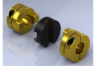
An Oldham coupling accommodates misalignment between shafts through its unique design, which consists of three main components:
- Two Hubs: Each hub is attached to the shaft of the connected equipment. The hubs have a series of slots around their circumference.
- Middle Block: The middle block fits between the two hubs and has perpendicular slots on its inner diameter. It connects the two hubs while allowing relative movement between them.
When the shafts experience angular or axial misalignment, the middle block slides within the slots of both hubs. The perpendicular slots on the middle block engage with the slots on the hubs, creating a parallelogram linkage.
This parallelogram linkage allows the Oldham coupling to compensate for angular misalignment by enabling the hubs to rotate independently about their own axes. The sliding action of the middle block accommodates axial misalignment by allowing the hubs to move slightly closer or farther apart.
The use of sliding contact instead of direct physical contact between the hubs minimizes friction, backlash, and wear, making the Oldham coupling an efficient and reliable method for transmitting torque while accommodating misalignment.
Overall, the Oldham coupling’s ability to handle both angular and axial misalignment ensures smooth and precise torque transmission between shafts, reducing stress on connected equipment and extending the lifespan of mechanical components.


editor by CX 2024-05-06
China manufacturer Custom CNC Turning Machining Spline Shaft Couplings Steering Shaft Coupler Oldham Coupling oldham coupling
Product Description
Custom CNC Turning Machining Spline Shaft Couplings Steering Shaft Coupler Oldham Coupling
Product Description
Coupling refers to a device that connects 2 shafts or shafts and rotating parts, rotates together during the transmission of motion and power, and does not disengage under normal conditions. Sometimes it is also used
as a safety device to prevent the connected parts from bearing excessive load, which plays the role of overload protection.
Couplings can be divided into rigid couplings and flexible couplings. Rigid couplings do not have buffering property and the ability to compensate the relative displacement of 2 axes. It is required that the 2 axes be strictly aligned. However, such couplings are simple in structure, low in manufacturing cost, convenient in assembly and disassembly, and maintenance, which can ensure that the 2 axes are relatively neutral, have large transmission torque, and are widely used. Commonly used are flange coupling, sleeve coupling and jacket coupling.
Flexible coupling can also be divided into flexible coupling without elastic element and flexible coupling with elastic element. The former type only has the ability to compensate the relative displacement of 2 axes, but cannot cushion and reduce vibration. Common types include slider coupling, gear coupling, universal coupling and chain coupling; The latter type contains elastic elements. In addition to the ability to compensate the relative displacement of 2 axes, it also has the functions of buffering and vibration reduction.
Our leading mainly including universal couplings, drum gear couplings, elastic couplings etc.
Main production equipments:
Large lathe, surface grinder, milling machine, spline milling machine, horizontal broaching machine, gear hobbing machine, shaper, slotting machine, bench drilling machine, radial drilling machine, boring machine, band sawing machine, horizontal lathe, end milling machine, crankshaft grinder, CNC milling machine, etc.
| Product Name | Custom CNC Turning Machining Spline Shaft Couplings Steering Shaft Coupler Oldham Coupling |
| Place of Origin | China |
| Certificates | SGS, ISO9001:2008 |
Coupling performance
1) Mobility. The movability of the coupling refers to the ability to compensate the relative displacement of 2 rotating components. Factors such as manufacturing and installation errors between connected components, temperature changes during operation and deformation under load all put CHINAMFG requirements for mobility. The movable performance compensates or alleviates the additional load between shafts, bearings, couplings and other components caused by the relative displacement between rotating components.
(2) Buffering. For the occasions where the load is often started or the working load changes, the coupling shall be equipped with elastic elements that play the role of cushioning and vibration reduction to protect the prime mover and the working machine from little or no damage.
(3) Safe, reliable, with sufficient strength and service life.
(4) Simple structure, easy to assemble, disassemble and maintain.
Inspection equipment:
Dynamic balance tester, high-speed intelligent carbon and sulfur analyzer, Blochon optical hardness tester, Leeb hardness tester, magnetic yoke flaw detector etc.
It is widely used in metallurgical steel rolling, wind power, hydropower, mining, engineering machinery, petrochemical, lifting, paper making, rubber, rail transit, shipbuilding and marine engineering and other industries.
How to select the appropriate coupling type
The following items should be considered when selecting the coupling type.
1. The size and nature of the required transmission torque, the requirements for buffering and damping functions, and whether resonance may occur.
2. The relative displacement of the axes of the 2 shafts is caused by manufacturing and assembly errors, shaft load and thermal expansion deformation, and relative movement between components.
3. Permissible overall dimensions and installation methods, and necessary operating space for assembly, adjustment and maintenance. For large couplings, they should be able to be disassembled without axial movement of the shaft.
In addition, the working environment, service life, lubrication, sealing, economy and other conditions should also be considered, and a suitable coupling type should be selected by referring to the characteristics of various couplings.
If you cannot determine the type, you can contact our professional engineer.
FAQ
Q: Why choose Shengao product?
A: We have our own factory, therefore, we can surely promise the quality of product and provide
you competitive price.
Q: Do you provide OEM Service?
A: Yes, we provide OEM Service.
Q: Do you provide customized machining parts?
A: Yes. Customers give us drawings and specifications, and we will produce accordingly.
Q: What is your payment term?
A: We provide kinds of payment terms such as L/C, T/T, Paypal, Escrow, etc.
If there’s anything we can help, please feel free to contact with us.
/* January 22, 2571 19:08:37 */!function(){function s(e,r){var a,o={};try{e&&e.split(“,”).forEach(function(e,t){e&&(a=e.match(/(.*?):(.*)$/))&&1
Specific Safety Considerations for Using Oldham Couplings in High-Speed Applications
When using Oldham couplings in high-speed applications, there are several safety considerations to keep in mind to ensure the safe and efficient operation of the machinery:
1. Material Selection: Choose high-quality materials for the Oldham coupling components to withstand the stresses and forces experienced at high speeds.
2. Proper Installation: Ensure the coupling is installed correctly and securely to prevent any chances of coupling failure or disengagement during high-speed operation.
3. Balancing: Balance the coupling components accurately to minimize vibration and prevent excessive wear, which can be more pronounced at high speeds.
4. Regular Inspections: Implement a regular inspection and maintenance schedule to identify any signs of wear, misalignment, or damage that may occur due to high-speed operation.
5. Lubrication: Use appropriate lubrication to reduce friction and heat generation, which is crucial in high-speed applications.
6. Temperature Consideration: Monitor the temperature of the coupling during operation as high speeds can result in increased heat generation.
7. Avoid Overloading: Do not exceed the recommended torque and speed limits specified by the manufacturer to avoid overloading the coupling.
8. Coupling Guards: Consider using coupling guards or covers to protect personnel from rotating or moving coupling components in high-speed systems.
9. Emergency Shutdown: Install an emergency shutdown system to quickly stop the machinery in case of coupling failure or other emergencies.
10. Compliance with Standards: Ensure that the Oldham coupling and its installation comply with industry standards and regulations for high-speed applications.
By adhering to these safety considerations and implementing preventive measures, the risk of accidents, machinery damage, and downtime in high-speed applications can be significantly reduced. Always consult the coupling manufacturer’s guidelines and follow best practices for safe operation and maintenance.

Are there Industry Standards or Certifications for Oldham Couplings?
Yes, there are industry standards and certifications that apply to Oldham couplings to ensure their quality, performance, and interchangeability. The most common standards and certifications related to couplings are set by organizations such as the American National Standards Institute (ANSI), the International Organization for Standardization (ISO), and the American Society of Mechanical Engineers (ASME). While these standards might not specifically focus on Oldham couplings, they often include requirements and guidelines that cover various types of flexible couplings, including Oldham couplings.
For example, ANSI B11.20: Safety Requirements for Integrated Manufacturing Systems establishes safety requirements for the design, construction, installation, operation, and maintenance of integrated manufacturing systems. Although not specific to Oldham couplings, this standard may encompass certain aspects of coupling safety.
Additionally, ISO 9001 certification is a widely recognized quality management system certification that many coupling manufacturers strive to achieve. This certification demonstrates a manufacturer’s commitment to producing high-quality products and adhering to rigorous quality control procedures.
When selecting an Oldham coupling, it is essential to check if the manufacturer complies with relevant industry standards and has obtained certifications that demonstrate their commitment to product quality and safety. It is also crucial to consider the specific requirements of your application and whether the chosen coupling meets those needs.
What is an Oldham Coupling and How Does It Function in Mechanical Systems?
An Oldham coupling is a type of flexible coupling used in mechanical systems to transmit torque between two shafts that are misaligned. It consists of three main components: two hubs or discs and a middle block. The two hubs are connected to the respective shafts, and the middle block sits in between them.
The key feature of the Oldham coupling is the middle block, which has slots on its opposite faces and is connected to the hubs using pins or keys. The slots in the middle block are oriented perpendicular to each other, allowing the middle block to move in a plane perpendicular to the axis of the shafts.
When torque is applied to one shaft, it is transmitted to the middle block of the coupling. Due to the slots, the middle block can slide laterally as the shafts rotate, accommodating both angular and axial misalignments between the shafts. This sliding action helps to reduce the reaction forces and wear that would otherwise occur in rigid couplings when misalignment is present.
Oldham couplings are known for their ability to provide constant velocity transmission even when misalignment exists. They do not have any backlash, which means there is minimal play between the coupling components during rotation. This feature makes them suitable for precision applications where accurate torque transmission and positioning are required.
One of the main advantages of the Oldham coupling is that it effectively isolates the connected shafts from each other, which can help in reducing vibrations and noise. Additionally, it can compensate for parallel misalignment between the shafts, making it ideal for applications where parallel shafts need to be connected while allowing some degree of misalignment.
Oldham couplings are commonly used in various industrial machinery and automation systems, including CNC machines, robotics, printing presses, and conveyor systems. They are particularly useful in applications where precise torque transmission, misalignment compensation, and low maintenance are essential.
editor by CX 2024-04-24
China Professional Custom CNC Turning Machining Spline Shaft Couplings Steering Shaft Coupler Oldham Coupling oldham coupling
Product Description
Custom CNC Turning Machining Spline Shaft Couplings Steering Shaft Coupler Oldham Coupling
Product Description
Coupling refers to a device that connects 2 shafts or shafts and rotating parts, rotates together during the transmission of motion and power, and does not disengage under normal conditions. Sometimes it is also used
as a safety device to prevent the connected parts from bearing excessive load, which plays the role of overload protection.
Couplings can be divided into rigid couplings and flexible couplings. Rigid couplings do not have buffering property and the ability to compensate the relative displacement of 2 axes. It is required that the 2 axes be strictly aligned. However, such couplings are simple in structure, low in manufacturing cost, convenient in assembly and disassembly, and maintenance, which can ensure that the 2 axes are relatively neutral, have large transmission torque, and are widely used. Commonly used are flange coupling, sleeve coupling and jacket coupling.
Flexible coupling can also be divided into flexible coupling without elastic element and flexible coupling with elastic element. The former type only has the ability to compensate the relative displacement of 2 axes, but cannot cushion and reduce vibration. Common types include slider coupling, gear coupling, universal coupling and chain coupling; The latter type contains elastic elements. In addition to the ability to compensate the relative displacement of 2 axes, it also has the functions of buffering and vibration reduction.
Our leading mainly including universal couplings, drum gear couplings, elastic couplings etc.
Main production equipments:
Large lathe, surface grinder, milling machine, spline milling machine, horizontal broaching machine, gear hobbing machine, shaper, slotting machine, bench drilling machine, radial drilling machine, boring machine, band sawing machine, horizontal lathe, end milling machine, crankshaft grinder, CNC milling machine, etc.
| Product Name | Custom CNC Turning Machining Spline Shaft Couplings Steering Shaft Coupler Oldham Coupling |
| Place of Origin | China |
| Certificates | SGS, ISO9001:2008 |
Coupling performance
1) Mobility. The movability of the coupling refers to the ability to compensate the relative displacement of 2 rotating components. Factors such as manufacturing and installation errors between connected components, temperature changes during operation and deformation under load all put CHINAMFG requirements for mobility. The movable performance compensates or alleviates the additional load between shafts, bearings, couplings and other components caused by the relative displacement between rotating components.
(2) Buffering. For the occasions where the load is often started or the working load changes, the coupling shall be equipped with elastic elements that play the role of cushioning and vibration reduction to protect the prime mover and the working machine from little or no damage.
(3) Safe, reliable, with sufficient strength and service life.
(4) Simple structure, easy to assemble, disassemble and maintain.
Inspection equipment:
Dynamic balance tester, high-speed intelligent carbon and sulfur analyzer, Blochon optical hardness tester, Leeb hardness tester, magnetic yoke flaw detector etc.
It is widely used in metallurgical steel rolling, wind power, hydropower, mining, engineering machinery, petrochemical, lifting, paper making, rubber, rail transit, shipbuilding and marine engineering and other industries.
How to select the appropriate coupling type
The following items should be considered when selecting the coupling type.
1. The size and nature of the required transmission torque, the requirements for buffering and damping functions, and whether resonance may occur.
2. The relative displacement of the axes of the 2 shafts is caused by manufacturing and assembly errors, shaft load and thermal expansion deformation, and relative movement between components.
3. Permissible overall dimensions and installation methods, and necessary operating space for assembly, adjustment and maintenance. For large couplings, they should be able to be disassembled without axial movement of the shaft.
In addition, the working environment, service life, lubrication, sealing, economy and other conditions should also be considered, and a suitable coupling type should be selected by referring to the characteristics of various couplings.
If you cannot determine the type, you can contact our professional engineer.
FAQ
Q: Why choose Shengao product?
A: We have our own factory, therefore, we can surely promise the quality of product and provide
you competitive price.
Q: Do you provide OEM Service?
A: Yes, we provide OEM Service.
Q: Do you provide customized machining parts?
A: Yes. Customers give us drawings and specifications, and we will produce accordingly.
Q: What is your payment term?
A: We provide kinds of payment terms such as L/C, T/T, Paypal, Escrow, etc.
If there’s anything we can help, please feel free to contact with us.
/* January 22, 2571 19:08:37 */!function(){function s(e,r){var a,o={};try{e&&e.split(“,”).forEach(function(e,t){e&&(a=e.match(/(.*?):(.*)$/))&&1
Specific Safety Considerations for Using Oldham Couplings in High-Speed Applications
When using Oldham couplings in high-speed applications, there are several safety considerations to keep in mind to ensure the safe and efficient operation of the machinery:
1. Material Selection: Choose high-quality materials for the Oldham coupling components to withstand the stresses and forces experienced at high speeds.
2. Proper Installation: Ensure the coupling is installed correctly and securely to prevent any chances of coupling failure or disengagement during high-speed operation.
3. Balancing: Balance the coupling components accurately to minimize vibration and prevent excessive wear, which can be more pronounced at high speeds.
4. Regular Inspections: Implement a regular inspection and maintenance schedule to identify any signs of wear, misalignment, or damage that may occur due to high-speed operation.
5. Lubrication: Use appropriate lubrication to reduce friction and heat generation, which is crucial in high-speed applications.
6. Temperature Consideration: Monitor the temperature of the coupling during operation as high speeds can result in increased heat generation.
7. Avoid Overloading: Do not exceed the recommended torque and speed limits specified by the manufacturer to avoid overloading the coupling.
8. Coupling Guards: Consider using coupling guards or covers to protect personnel from rotating or moving coupling components in high-speed systems.
9. Emergency Shutdown: Install an emergency shutdown system to quickly stop the machinery in case of coupling failure or other emergencies.
10. Compliance with Standards: Ensure that the Oldham coupling and its installation comply with industry standards and regulations for high-speed applications.
By adhering to these safety considerations and implementing preventive measures, the risk of accidents, machinery damage, and downtime in high-speed applications can be significantly reduced. Always consult the coupling manufacturer’s guidelines and follow best practices for safe operation and maintenance.

How do Temperature and Environmental Conditions Affect the Performance of an Oldham Coupling?
The performance of an Oldham coupling can be influenced by temperature and environmental conditions. The choice of materials used in the coupling’s construction plays a vital role in determining its suitability for specific operating environments. Here are some factors to consider:
Temperature: Extreme temperatures can affect the material properties of the Oldham coupling components. High temperatures can lead to thermal expansion, which might cause changes in the coupling’s dimensions and interfere with its performance. In contrast, low temperatures can make materials more brittle, reducing the coupling’s ability to withstand torque and misalignment. It is essential to select materials that can operate effectively within the temperature range of the intended application.
Corrosive Environments: In corrosive environments, such as chemical processing plants or marine applications, it is crucial to use materials that are resistant to corrosion. Stainless steel and other corrosion-resistant alloys are commonly used in such conditions to ensure the longevity and reliability of the Oldham coupling.
Dust and Contaminants: Dust, dirt, and other contaminants can accumulate on the coupling’s moving parts, leading to increased wear and reduced performance. Regular cleaning and maintenance are essential in environments where dust and contaminants are prevalent.
Humidity and Moisture: High humidity or moisture can lead to the formation of rust or corrosion on metal components. For applications in such environments, it is essential to use materials with proper corrosion resistance or consider protective coatings.
Shock and Vibration: In applications where the coupling is subjected to high levels of shock and vibration, it is essential to ensure that the coupling’s design and materials can withstand these dynamic forces without premature failure.
Proper selection of materials and regular maintenance can help mitigate the impact of temperature and environmental conditions on the performance of an Oldham coupling. Additionally, consulting with coupling manufacturers or engineering experts can provide valuable insights into choosing the most suitable coupling for specific operating conditions.
Installation and Maintenance of Oldham Couplings
Proper installation and maintenance are crucial for ensuring the optimal performance and longevity of an Oldham coupling. Here are the steps to install and maintain an Oldham coupling:
Installation:
- 1. Inspect the Components: Before installation, carefully inspect the Oldham coupling’s hubs and center disc for any signs of damage or wear.
- 2. Shaft Preparation: Ensure that the shafts are clean and free from any debris or burrs. Make sure the shaft diameters match the hub bores and keyway dimensions.
- 3. Center Disc Alignment: Align the center disc with the two hubs so that the slots or keyways on the center disc fit into the corresponding slots on the hubs.
- 4. Secure the Hubs: Slide the hubs onto the shafts and fasten them securely using appropriate fasteners such as screws or clamps.
- 5. Tighten Fasteners: Carefully tighten the fasteners according to the manufacturer’s recommendations. Be cautious not to over-torque, as it may lead to distortion or damage to the components.
- 6. Check Misalignment: Verify that the Oldham coupling can accommodate the required misalignment between the shafts without binding or excessive stress.
Maintenance:
- 1. Regular Inspection: Periodically inspect the Oldham coupling for signs of wear, damage, or misalignment. Look for any unusual noises or vibrations during operation.
- 2. Lubrication: Some Oldham couplings may require periodic lubrication for smooth operation. Check the manufacturer’s guidelines for the proper type and amount of lubricant.
- 3. Replace Worn Components: If any part of the Oldham coupling shows significant wear or damage, replace it with a new component from the original equipment manufacturer (OEM).
- 4. Alignment Check: Regularly check the alignment of the shafts and the coupling to ensure that the misalignment is within the specified limits.
- 5. Environmental Considerations: Take into account the operating environment, such as temperature and humidity, and use appropriate materials and coatings to resist corrosion and wear.
- 6. Follow Manufacturer Guidelines: Always adhere to the manufacturer’s installation, operation, and maintenance instructions to ensure safe and efficient coupling performance.
By following these installation and maintenance practices, an Oldham coupling can provide reliable torque transmission, compensate for misalignment, and contribute to the smooth operation of the connected machinery or equipment.
editor by CX 2024-03-08
China OEM Flexible Flex Fluid Chain Jaw Flange Gear Rigid Spacer Pin HRC Mh Nm Universal Fenaflex Oldham Spline Clamp Tyre Grid Hydraulic Servo Motor Shaft Coupling oldham coupling
Product Description
Flexible Flex Fluid Chain Jaw Flange Gear Rigid Spacer Pin HRC Mh Nm Universal Fenaflex Oldham Spline Clamp Tyre Grid Hydraulic Servo Motor Shaft Coupling
Features
Material: cast iron GG25, GG20 steel: C45
Parts: 2 couplings and 1 tire body.
Size from F40-F250. and Type: “B”, “F”, “H”.
Working temp: -20~80ºC
Transmission torque:10-20000N.M
Axial misalignment: D*2%
Radial deviation: D*1%
Angular misalignment:3°-6°
Application: tire couplings are usually used in wet, dusty, under attract, vibration, rotating, and complex working conditions. like: diesel pump
Installation: easy on, easy off.
Maintenance: no need for lubricating and durability.
Product Description
| Size | Type | Bush No. | MaxBore | Type F&H | Type H | Serve over Key |
A | C | D | F | M | |||
| mm | Inch | L | E | L | E | |||||||||
| F40 | B | – | 32 | – | – | – | 33 | 22 | M5 | 104 | 82 | – | – | 11 |
| F40 | F | 1008 | 25 | 1″ | 33 | 22 | – | – | – | 104 | 82 | – | – | 11 |
| F40 | H | 1008 | 25 | 1″ | 33 | 22 | – | – | – | 104 | 82 | – | – | 11 |
| F50 | B | – | 38 | – | – | – | 43 | 32 | M5 | 133 | 100 | 79 | – | 12.5 |
| F50 | F | 1210 | 32 | 1 1/4″ | 38 | 25 | – | – | – | 133 | 100 | 79 | – | 12.5 |
| F50 | H | 1210 | 32 | 1 1/4″ | 38 | 25 | – | – | – | 133 | 100 | 79 | – | 12.5 |
| F80 | B | – | 45 | – | – | – | 55 | 33 | M6 | 165 | 125 | 70 | – | 16.5 |
| F80 | F | 1610 | 42 | 1 5/8″ | 42 | 25 | – | – | – | 165 | 125 | 103 | – | 16.5 |
| F60 | H | 1610 | 42 | 1 5/8″ | 42 | 25 | – | – | – | 165 | 125 | 103 | – | 16.6 |
| F70 | B | – | 50 | – | – | – | 47 | 35 | M8 | 187 | 142 | 80 | 60 | 11.5 |
| F70 | F | 2012 | 50 | 2″ | 44 | 32 | – | – | – | 187 | 142 | 80 | 50 | 11.5 |
| F70 | H | 1810 | 42 | 1 5/8″ | 42 | 25 | – | – | – | 187 | 142 | 80 | 50 | 11.5 |
| F80 | B | – | 60 | – | – | – | 55 | 42 | M8 | 211 | 165 | 98 | 54 | 12.5 |
| F80 | F | 2517 | 80 | 2 1/2″ | 58 | 45 | – | – | – | 211 | 165 | 98 | 54 | 12.5 |
| F80 | H | 2012 | 50 | 2″ | 45 | 32 | – | – | – | 211 | 165 | 98 | 54 | 12.5 |
| F90 | H | – | 70 | – | – | – | 63.5 | 49 | M10 | 235 | 188 | 108 | 62 | 13.5 |
| F90 | F | 2517 | 60 | 2 1/2″ | 58.5 | 45 | – | – | – | 235 | 188 | 108 | 62 | 13.5 |
| F90 | H | 2517 | 60 | 2 1/2″ | 58.5 | 45 | – | – | – | 235 | 188 | 108 | 62 | 13.5 |
| F100 | H | – | 80 | – | – | – | 63.5 | 49 | M10 | 235 | 188 | 120 | 62 | 13.5 |
| F100 | F | 3571 | 75 | 3″ | 64.5 | 51 | – | – | – | 235 | 188 | 125 | 62 | 13.5 |
| F100 | H | 2517 | 60 | 2 1/2″ | 58.5 | 45 | – | – | – | 235 | 188 | 113 | 62 | 13.5 |
| F110 | B | – | 90 | – | – | – | 75.5 | 63 | M12 | 279 | 233 | 128 | 62 | 12.5 |
| F110 | F | 3571 | 75 | 3″ | 63.5 | 51 | – | – | – | 279 | 233 | 134 | 62 | 12.5 |
| F110 | H | 3571 | 75 | 3″ | 63.5 | 51 | – | – | – | 279 | 233 | 134 | 62 | 12.5 |
| F120 | B | – | 100 | – | – | – | 84.5 | 70 | M12 | 314 | 264 | 140 | 67 | 14.5 |
| F120 | F | 3525 | 100 | 4″ | 79.5 | 65 | – | – | – | 314 | 264 | 144 | 67 | 14.5 |
| F120 | H | 3571 | 75 | 4″ | 85.5 | 51 | – | – | – | 314 | 264 | 144 | 67 | 14.5 |
| F140 | B | – | 130 | – | – | – | 110.5 | 4 | M16 | 359 | 311 | 178 | 73 | 16 |
| F140 | F | 3525 | 100 | 4″ | 81.5 | 65 | – | – | – | 359 | 311 | 178 | 73 | 16 |
| F140 | H | 3525 | 100 | 4″ | 81.5 | 65 | – | – | – | 359 | 311 | 178 | 73 | 18 |
| F160 | B | – | 140 | – | – | – | 117 | 102 | M20 | 402 | 345 | 187 | 78 | 16 |
| F160 | F | 4030 | 115 | 4 1/2″ | 92 | 77 | – | – | – | 402 | 345 | 197 | 78 | 16 |
| F160 | H | 4030 | 115 | 4 1/2″ | 92 | 77 | – | – | – | 402 | 345 | 197 | 78 | 16 |
| F180 | B | – | 150 | – | – | – | 137 | 114 | M16 | 470 | 394 | 205 | 94 | 23 |
| F180 | F | 4536 | 125 | 5″ | 112 | 89 | – | – | – | 470 | 394 | 205 | 94 | 23 |
| F180 | H | 4535 | 125 | 5″ | 112 | 89 | – | – | – | 470 | 394 | 205 | 94 | 23 |
| F200 | B | – | 150 | – | – | – | 138 | 114 | M20 | 508 | 429 | 205 | 103 | 24 |
| F200 | F | 4535 | 125 | 5″ | 113 | 89 | – | – | – | 508 | 429 | 205 | 103 | 24 |
| F200 | H | 4535 | 125 | 5″ | 113 | 89 | – | – | 508 | 429 | 205 | 103 | 24 | |
| F220 | B | – | 160 | – | – | – | 154.5 | 127 | M20 | 562 | 474 | 223 | 118 | 27.5 |
| F220 | F | 5571 | 125 | 5″ | 129.5 | 102 | – | – | – | 562 | 474 | 223 | 118 | 27.5 |
| F220 | H | 5571 | 125 | 5″ | 129.5 | 102 | – | – | – | 562 | 474 | 223 | 118 | 27.5 |
| F250 | H | – | 190 | – | – | 161.5 | 132 | M20 | 628 | 522 | 254 | 125 | 29.5 | |
Related Products
Company Profile
FAQ
Q: How to ship to us?
A: It is available by air, sea, or train.
Q: How to pay the money?
A: T/T and L/C are preferred, with different currencies, including USD, EUR, RMB, etc.
Q: How can I know if the product is suitable for me?
A: >1ST confirm drawing and specification >2nd test sample >3rd start mass production.
Q: Can I come to your company to visit?
A: Yes, you are welcome to visit us at any time.

Can an Oldham Coupling Reduce Vibration and Backlash in Mechanical Systems?
Yes, an Oldham coupling can help reduce vibration and minimize backlash in mechanical systems, making it a popular choice for applications that require precise and smooth power transmission.
Vibration Reduction: Oldham couplings are designed with a three-piece construction, comprising two hubs and a center disc. The center disc, also known as the spacer, is made of a flexible material such as acetal or nylon. When torque is transmitted through the coupling, the center disc flexes, absorbing any misalignment between the shafts. This flexing action helps dampen vibration and reduces resonance in the system, leading to smoother operation and less mechanical stress on connected components.
Backlash Minimization: Backlash is the amount of play or free movement between the mating parts of a mechanical system. In traditional couplings like gear couplings, there can be significant backlash due to the nature of the gear teeth. However, Oldham couplings have a unique design that allows them to transmit torque with minimal backlash. The center disc provides a small amount of clearance between the hubs, enabling smooth rotation without backlash. This characteristic is especially beneficial in applications that require precise motion control, such as robotics and CNC machines.
Overall, the flexible and backlash-free nature of Oldham couplings makes them well-suited for applications where vibration reduction and precise motion control are essential. By reducing vibration and backlash, Oldham couplings contribute to the overall efficiency, accuracy, and reliability of the mechanical system they are employed in.
Real-World Examples of Oldham Coupling Usage in Mechanical Engineering
Oldham couplings are widely used in various mechanical engineering applications due to their ability to transmit torque while compensating for angular misalignment. Here are some real-world examples of Oldham coupling usage:
- Packaging Machinery: Oldham couplings are commonly employed in packaging machines that require precise and continuous motion. These couplings help connect the motor shaft to various components in the packaging process, such as conveyor belts, rollers, and cutting blades.
- Automated Assembly Lines: In automated assembly lines, Oldham couplings are utilized to transfer torque from the motor to the robotic arms or handling mechanisms. The couplings enable smooth and accurate movement, ensuring precise positioning of components during assembly.
- Printing Equipment: Printing machines utilize Oldham couplings to transmit power from the motors to the printing cylinders and rollers. The couplings accommodate any misalignment between the shafts and minimize vibration, resulting in improved print quality.
- Material Handling Systems: Material handling systems, such as conveyor systems, use Oldham couplings to connect drive motors to the conveyor belts. These couplings facilitate the efficient transfer of goods while compensating for any misalignment that may occur during operation.
- Industrial Pumps: Oldham couplings are employed in industrial pumps to transfer power from the motor to the pump impeller. They aid in absorbing vibration and maintaining alignment, which is crucial for the pump’s optimal performance and longevity.
- Medical Devices: Some medical devices, such as scanning equipment and diagnostic machines, incorporate Oldham couplings to ensure precise and reliable motion, contributing to accurate medical imaging and diagnosis.
These examples demonstrate the versatility of Oldham couplings in various mechanical engineering applications. Their ability to handle misalignment, reduce vibration, and transmit torque makes them a valuable component in many industrial sectors.
Installation and Maintenance of Oldham Couplings
Proper installation and maintenance are crucial for ensuring the optimal performance and longevity of an Oldham coupling. Here are the steps to install and maintain an Oldham coupling:
Installation:
- 1. Inspect the Components: Before installation, carefully inspect the Oldham coupling’s hubs and center disc for any signs of damage or wear.
- 2. Shaft Preparation: Ensure that the shafts are clean and free from any debris or burrs. Make sure the shaft diameters match the hub bores and keyway dimensions.
- 3. Center Disc Alignment: Align the center disc with the two hubs so that the slots or keyways on the center disc fit into the corresponding slots on the hubs.
- 4. Secure the Hubs: Slide the hubs onto the shafts and fasten them securely using appropriate fasteners such as screws or clamps.
- 5. Tighten Fasteners: Carefully tighten the fasteners according to the manufacturer’s recommendations. Be cautious not to over-torque, as it may lead to distortion or damage to the components.
- 6. Check Misalignment: Verify that the Oldham coupling can accommodate the required misalignment between the shafts without binding or excessive stress.
Maintenance:
- 1. Regular Inspection: Periodically inspect the Oldham coupling for signs of wear, damage, or misalignment. Look for any unusual noises or vibrations during operation.
- 2. Lubrication: Some Oldham couplings may require periodic lubrication for smooth operation. Check the manufacturer’s guidelines for the proper type and amount of lubricant.
- 3. Replace Worn Components: If any part of the Oldham coupling shows significant wear or damage, replace it with a new component from the original equipment manufacturer (OEM).
- 4. Alignment Check: Regularly check the alignment of the shafts and the coupling to ensure that the misalignment is within the specified limits.
- 5. Environmental Considerations: Take into account the operating environment, such as temperature and humidity, and use appropriate materials and coatings to resist corrosion and wear.
- 6. Follow Manufacturer Guidelines: Always adhere to the manufacturer’s installation, operation, and maintenance instructions to ensure safe and efficient coupling performance.
By following these installation and maintenance practices, an Oldham coupling can provide reliable torque transmission, compensate for misalignment, and contribute to the smooth operation of the connected machinery or equipment.
editor by CX 2023-09-28
China high quality Flexible Flex Fluid Chain Jaw Flange Gear Rigid Spacer Pin HRC Mh Nm Universal Fenaflex Oldham Spline Clamp Tyre Grid Hydraulic Servo Motor Shaft Coupling oldham coupling
Product Description
Flexible flex Fluid Chain Jaw flange Gear Rigid Spacer PIN HRC MH NM universal Fenaflex Oldham spline clamp tyre grid hydraulic servo motor shaft Coupling
Product Description
The function of Shaft coupling:
1. Shafts for connecting separately manufactured units such as motors and generators.
2. If any axis is misaligned.
3. Provides mechanical flexibility.
4. Absorb the transmission of impact load.
5. Prevent overload
We can provide the following couplings.
| Rigid coupling | Flange coupling | Oldham coupling |
| Sleeve or muff coupling | Gear coupling | Bellow coupling |
| Split muff coupling | Flexible coupling | Fluid coupling |
| Clamp or split-muff or compression coupling | Universal coupling | Variable speed coupling |
| Bushed pin-type coupling | Diaphragm coupling | Constant speed coupling |
Company Profile
We are an industrial company specializing in the production of couplings. It has 3 branches: steel casting, forging, and heat treatment. Main products: cross shaft universal coupling, drum gear coupling, non-metallic elastic element coupling, rigid coupling, etc.
The company mainly produces the industry standard JB3241-91 swap JB5513-91 swc. JB3242-93 swz series universal coupling with spider type. It can also design and produce various non-standard universal couplings, other couplings, and mechanical products for users according to special requirements. Currently, the products are mainly sold to major steel companies at home and abroad, the metallurgical steel rolling industry, and leading engine manufacturers, with an annual production capacity of more than 7000 sets.
The company’s quality policy is “quality for survival, variety for development.” In August 2000, the national quality system certification authority audited that its quality assurance system met the requirements of GB/T19002-1994 IDT ISO9002:1994 and obtained the quality system certification certificate with the registration number 0900B5711. It is the first enterprise in the coupling production industry in HangZhou City that passed the ISO9002 quality and constitution certification.
The company pursues the business purpose of “reliable quality, the supremacy of reputation, commitment to business and customer satisfaction” and welcomes customers at home and abroad to choose our products.
At the same time, the company has established long-term cooperative relations with many enterprises and warmly welcomes friends from all walks of life to visit, investigate and negotiate business!
How to use the coupling safely
The coupling is an intermediate connecting part of each motion mechanism, which directly impacts the regular operation of each motion mechanism. Therefore, attention must be paid to:
1. The coupling is not allowed to have more than the specified axis deflection and radial displacement so as not to affect its transmission performance.
2. The bolts of the LINS coupling shall not be loose or damaged.
3. Gear coupling and cross slide coupling shall be lubricated regularly, and lubricating grease shall be added every 2-3 months to avoid severe wear of gear teeth and serious consequences.
4. The tooth width contact length of gear coupling shall not be less than 70%; Its axial displacement shall not be more significant than 5mm
5. The coupling is not allowed to have cracks. If there are cracks, it needs to be replaced (they can be knocked with a small hammer and judged according to the sound).
6. The keys of LINS coupling shall be closely matched and shall not be loosened.
7. The tooth thickness of the gear coupling is worn. When the lifting mechanism exceeds 15% of the original tooth thickness, the operating mechanism exceeds 25%, and the broken tooth is also scrapped.
8. If the elastic ring of the pin coupling and the sealing ring of the gear coupling is damaged or aged, they should be replaced in time.
Certifications
Packaging & Shipping
Can an Oldham Coupling Reduce Vibration and Backlash in Mechanical Systems?
Yes, an Oldham coupling can help reduce vibration and minimize backlash in mechanical systems, making it a popular choice for applications that require precise and smooth power transmission.
Vibration Reduction: Oldham couplings are designed with a three-piece construction, comprising two hubs and a center disc. The center disc, also known as the spacer, is made of a flexible material such as acetal or nylon. When torque is transmitted through the coupling, the center disc flexes, absorbing any misalignment between the shafts. This flexing action helps dampen vibration and reduces resonance in the system, leading to smoother operation and less mechanical stress on connected components.
Backlash Minimization: Backlash is the amount of play or free movement between the mating parts of a mechanical system. In traditional couplings like gear couplings, there can be significant backlash due to the nature of the gear teeth. However, Oldham couplings have a unique design that allows them to transmit torque with minimal backlash. The center disc provides a small amount of clearance between the hubs, enabling smooth rotation without backlash. This characteristic is especially beneficial in applications that require precise motion control, such as robotics and CNC machines.
Overall, the flexible and backlash-free nature of Oldham couplings makes them well-suited for applications where vibration reduction and precise motion control are essential. By reducing vibration and backlash, Oldham couplings contribute to the overall efficiency, accuracy, and reliability of the mechanical system they are employed in.

What are the Maintenance Requirements for Oldham Couplings to Ensure Their Longevity?
Maintaining Oldham couplings is essential to ensure their longevity and optimal performance. Proper maintenance practices can prevent premature wear and damage, reducing the risk of unexpected failures and downtime. Here are some maintenance requirements to consider for Oldham couplings:
- Regular Inspection: Perform regular visual inspections of the coupling to check for signs of wear, misalignment, or damage. Look for cracks, corrosion, or any unusual behavior during operation.
- Lubrication: Oldham couplings may require periodic lubrication to reduce friction between moving parts and prevent excessive wear. Check the manufacturer’s guidelines for the appropriate lubrication schedule and type of lubricant to use.
- Alignment: Proper alignment is crucial for Oldham couplings to function correctly. Ensure that the shafts and hubs are correctly aligned to avoid additional stress on the coupling components.
- Torque Check: Periodically check the coupling’s torque to verify that it is within the recommended operating range. Over-torqueing or under-torqueing can lead to coupling failure.
- Environmental Protection: In harsh environments or applications exposed to contaminants, consider using protective covers or enclosures to shield the coupling from debris, dirt, and moisture.
- Replacement of Worn Parts: If any component of the Oldham coupling shows signs of wear or damage, promptly replace it with a new one from the manufacturer.
- Proper Handling: During installation or maintenance, handle the coupling components with care to avoid any accidental damage.
It is crucial to follow the manufacturer’s maintenance guidelines and recommendations specific to the Oldham coupling model being used. Proper maintenance practices will not only extend the coupling’s lifespan but also contribute to the overall reliability and efficiency of the mechanical system it is part of.
Installation and Maintenance of Oldham Couplings
Proper installation and maintenance are crucial for ensuring the optimal performance and longevity of an Oldham coupling. Here are the steps to install and maintain an Oldham coupling:
Installation:
- 1. Inspect the Components: Before installation, carefully inspect the Oldham coupling’s hubs and center disc for any signs of damage or wear.
- 2. Shaft Preparation: Ensure that the shafts are clean and free from any debris or burrs. Make sure the shaft diameters match the hub bores and keyway dimensions.
- 3. Center Disc Alignment: Align the center disc with the two hubs so that the slots or keyways on the center disc fit into the corresponding slots on the hubs.
- 4. Secure the Hubs: Slide the hubs onto the shafts and fasten them securely using appropriate fasteners such as screws or clamps.
- 5. Tighten Fasteners: Carefully tighten the fasteners according to the manufacturer’s recommendations. Be cautious not to over-torque, as it may lead to distortion or damage to the components.
- 6. Check Misalignment: Verify that the Oldham coupling can accommodate the required misalignment between the shafts without binding or excessive stress.
Maintenance:
- 1. Regular Inspection: Periodically inspect the Oldham coupling for signs of wear, damage, or misalignment. Look for any unusual noises or vibrations during operation.
- 2. Lubrication: Some Oldham couplings may require periodic lubrication for smooth operation. Check the manufacturer’s guidelines for the proper type and amount of lubricant.
- 3. Replace Worn Components: If any part of the Oldham coupling shows significant wear or damage, replace it with a new component from the original equipment manufacturer (OEM).
- 4. Alignment Check: Regularly check the alignment of the shafts and the coupling to ensure that the misalignment is within the specified limits.
- 5. Environmental Considerations: Take into account the operating environment, such as temperature and humidity, and use appropriate materials and coatings to resist corrosion and wear.
- 6. Follow Manufacturer Guidelines: Always adhere to the manufacturer’s installation, operation, and maintenance instructions to ensure safe and efficient coupling performance.
By following these installation and maintenance practices, an Oldham coupling can provide reliable torque transmission, compensate for misalignment, and contribute to the smooth operation of the connected machinery or equipment.
editor by CX 2023-09-05
China Hot selling Custom CNC Turning Machining Spline Shaft Couplings Steering Shaft Coupler Oldham Coupling oldham coupling
Product Description
Custom CNC Turning Machining Spline Shaft Couplings Steering Shaft Coupler Oldham Coupling
Coupling refers to a device that connects 2 shafts or shafts and rotating parts, rotates together during the transmission of motion and power, and does not disengage under normal conditions. Sometimes it is also used
as a safety device to prevent the connected parts from bearing excessive load, which plays the role of overload protection.
Couplings can be divided into rigid couplings and flexible couplings. Rigid couplings do not have buffering property and the ability to compensate the relative displacement of 2 axes. It is required that the 2 axes be strictly aligned. However, such couplings are simple in structure, low in manufacturing cost, convenient in assembly and disassembly, and maintenance, which can ensure that the 2 axes are relatively neutral, have large transmission torque, and are widely used. Commonly used are flange coupling, sleeve coupling and jacket coupling.
Flexible coupling can also be divided into flexible coupling without elastic element and flexible coupling with elastic element. The former type only has the ability to compensate the relative displacement of 2 axes, but cannot cushion and reduce vibration. Common types include slider coupling, gear coupling, universal coupling and chain coupling; The latter type contains elastic elements. In addition to the ability to compensate the relative displacement of 2 axes, it also has the functions of buffering and vibration reduction.
Our leading mainly including universal couplings, drum gear couplings, elastic couplings etc.
Main production equipments:
Large lathe, surface grinder, milling machine, spline milling machine, horizontal broaching machine, gear hobbing machine, shaper, slotting machine, bench drilling machine, radial drilling machine, boring machine, band sawing machine, horizontal lathe, end milling machine, crankshaft grinder, CNC milling machine, etc.
Coupling performance
1) Mobility. The movability of the coupling refers to the ability to compensate the relative displacement of 2 rotating components. Factors such as manufacturing and installation errors between connected components, temperature changes during operation and deformation under load all put CZPT requirements for mobility. The movable performance compensates or alleviates the additional load between shafts, bearings, couplings and other components caused by the relative displacement between rotating components.
(2) Buffering. For the occasions where the load is often started or the working load changes, the coupling shall be equipped with elastic elements that play the role of cushioning and vibration reduction to protect the prime mover and the working machine from little or no damage.
(3) Safe, reliable, with sufficient strength and service life.
(4) Simple structure, easy to assemble, disassemble and maintain.
Inspection equipment:
Dynamic balance tester, high-speed intelligent carbon and sulfur analyzer, Blochon optical hardness tester, Leeb hardness tester, magnetic yoke flaw detector etc.
It is widely used in metallurgical steel rolling, wind power, hydropower, mining, engineering machinery, petrochemical, lifting, paper making, rubber, rail transit, shipbuilding and marine engineering and other industries.
How to select the appropriate coupling type
The following items should be considered when selecting the coupling type.
1. The size and nature of the required transmission torque, the requirements for buffering and damping functions, and whether resonance may occur.
2. The relative displacement of the axes of the 2 shafts is caused by manufacturing and assembly errors, shaft load and thermal expansion deformation, and relative movement between components.
3. Permissible overall dimensions and installation methods, and necessary operating space for assembly, adjustment and maintenance. For large couplings, they should be able to be disassembled without axial movement of the shaft.
In addition, the working environment, service life, lubrication, sealing, economy and other conditions should also be considered, and a suitable coupling type should be selected by referring to the characteristics of various couplings.
If you cannot determine the type, you can contact our professional engineer.
Q: Why choose Shengao product?
A: We have our own factory, therefore, we can surely promise the quality of product and provide
you competitive price.
Q: Do you provide OEM Service?
A: Yes, we provide OEM Service.
Q: Do you provide customized machining parts?
A: Yes. Customers give us drawings and specifications, and we will produce accordingly.
Q: What is your payment term?
A: We provide kinds of payment terms such as L/C, T/T, Paypal, Escrow, etc.
If there’s anything we can help, please feel free to contact with us.
How to Identify Signs of Wear or Damage in an Oldham Coupling?
Regular inspection of Oldham couplings is essential to ensure their proper functioning and prevent unexpected failures. Here are some signs of wear or damage to look for during the inspection:
1. Visible Cracks or Deformation: Check the center disc and the hubs for any visible cracks, tears, or deformation. These can be indicators of excessive stress or misalignment.
2. Abnormal Vibrations: Excessive vibrations during operation may suggest that the coupling is not functioning correctly. It could be due to wear in the center disc or improper installation.
3. Unusual Noise: Grinding, clicking, or banging noises during equipment operation may indicate that the Oldham coupling is experiencing excessive backlash or misalignment.
4. Increased Backlash: If there is noticeable play or free movement between the coupling components, it may be a sign of wear in the center disc or worn hubs.
5. Reduced Performance: A decrease in the performance of the machinery or unexpected issues with power transmission could be indicative of coupling problems.
6. Abnormal Heating: If the coupling becomes unusually hot during operation, it may suggest friction or misalignment issues.
7. Excessive Wear on Center Disc: Inspect the center disc for signs of wear, such as grooves, uneven surfaces, or material loss. This may occur over time due to the repeated flexing of the disc.
8. Lubrication Issues: Improper or inadequate lubrication can lead to increased friction and wear in the coupling components.
If any of these signs are observed during the inspection, it is essential to address the issue promptly. Depending on the severity of the wear or damage, the Oldham coupling may require replacement or repair. Regular maintenance and proper lubrication can help extend the life of the coupling and prevent unexpected failures, ensuring smooth and reliable operation in the machinery or equipment.
Can an Oldham Coupling be Used in Precision Motion Control Applications?
Yes, an Oldham coupling can be used in precision motion control applications. Oldham couplings are known for their ability to provide constant velocity transmission while accommodating misalignment. These couplings offer low backlash and minimal hysteresis, making them suitable for precision motion control systems.
Precision motion control applications require accurate and repeatable motion, which can be achieved by using an Oldham coupling. The coupling’s design allows it to handle angular misalignment without introducing significant axial or radial forces. This feature helps maintain the accuracy and integrity of the motion control system.
Oldham couplings are often used in applications such as robotics, CNC machines, optical equipment, and other systems where precise positioning and smooth motion are essential. Their ability to reduce vibration and minimize backlash is particularly beneficial in these applications, as it enhances the system’s overall performance and accuracy.
When selecting an Oldham coupling for precision motion control, it is essential to consider factors such as the required torque capacity, speed, and shaft sizes. Additionally, regular maintenance and proper alignment are crucial to ensure the coupling’s optimal performance in precision applications.
Transmission of Torque in Oldham Couplings
An Oldham coupling is designed to transmit torque between two shafts that are misaligned but parallel to each other. It consists of three components: two hubs (also known as drive hubs) and a center disc. The hubs are connected to their respective shafts, while the center disc sits between them.
The center disc of the Oldham coupling is characterized by slots or keyways on its opposite sides, which engage with the hubs. The slots allow the center disc to slide or float within the hubs while maintaining a constant angular velocity between the shafts.
When torque is applied to the drive hub on one side, it induces a rotational force on the center disc. This rotational force is then transferred to the other drive hub, which results in torque transmission to the second shaft. The center disc acts as an intermediary between the two hubs, compensating for any axial or radial misalignment between the shafts.
Regarding the question of different shaft diameters, the Oldham coupling can accommodate shafts with different diameters as long as the hub design allows for a secure connection. The keyways or slots in the center disc and hubs should be compatible with the shaft dimensions to ensure proper torque transmission and to prevent slippage or damage.
It is essential to select the appropriate size and design of the Oldham coupling to match the shaft diameters and to ensure reliable torque transmission while accommodating any misalignment between the shafts.
editor by CX 2023-08-07
Fluid shop Coupling Chain Jaw Flexible Flange Gear Rigid Spacer Spacer Motor Shaft Universal Half Reducer Spline Stainless Steel Elastomeric Servo with ce certificate top quality low price
Product Description
CZPT CZPT Chain Jaw Flexible flange Gear Rigid CZPT r Fenaflex CZPT r motor shaft CZPT half oldham reducer spline stainless steel elastomeric servo

Gear supplier Coupling Flange Rigid Pin Spacer HRC Mh Nm Spacer Motor Shaft Universal Half Reducer Spline Tyre Drive Grid Mechanical Elastomeric with ce certificate top quality low price
Product Description
Gear CZPT Flange Rigid Pin CZPT r HRC Mh Nm CZPT r CZPT Shaft CZPT Half Reducer Spline Tyre CZPT Grid CZPT Elastomeric
Fluid supplier Coupling Chainflexible Flange Gear Rigid Spacer Spacer Motor Shaft Universal Reducer Spline Stainless Steel Mechanical Elastomeric Clamp with ce certificate top quality low price
Product Description
Fluid CZPT Chainflexible Flange Gear Rigid CZPT r CZPT r CZPT Shaft CZPT Reducer Spline CZPT Steel CZPT Elastomeric Clamp
Flexible near me shop Coupling Flange Gear Rigid Pin Spacer Spacer Motor Shaft Universal Half Reducer Spline Tyre Drive Grid Hydraulic Stainless Steel with ce certificate top quality low price
Product Description
Flexible CZPT Flange Gear Rigid Pin CZPT r CZPT r CZPT Shaft CZPT Half Reducer Spline Tyre CZPT Grid CZPT ulic CZPT Steel