Product Description
Flexible Flex Fluid Chain Jaw Flange Gear Rigid Spacer Pin HRC Mh Nm Universal Fenaflex Oldham Spline Clamp Tyre Grid Hydraulic Servo Motor Shaft Coupling
Features
Material: cast iron GG25, GG20 steel: C45
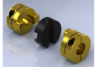
Parts: 2 couplings and 1 tire body.
Size from F40-F250. and Type: “B”, “F”, “H”.
Working temp: -20~80ºC
Transmission torque:10-20000N.M
Axial misalignment: D*2%
Radial deviation: D*1%
Angular misalignment:3°-6°
Application: tire couplings are usually used in wet, dusty, under attract, vibration, rotating, and complex working conditions. like: diesel pump
Installation: easy on, easy off.
Maintenance: no need for lubricating and durability.
Product Description
| Size | Type | Bush No. | MaxBore | Type F&H | Type H | Serve over Key |
A | C | D | F | M | |||
| mm | Inch | L | E | L | E | |||||||||
| F40 | B | – | 32 | – | – | – | 33 | 22 | M5 | 104 | 82 | – | – | 11 |
| F40 | F | 1008 | 25 | 1″ | 33 | 22 | – | – | – | 104 | 82 | – | – | 11 |
| F40 | H | 1008 | 25 | 1″ | 33 | 22 | – | – | – | 104 | 82 | – | – | 11 |
| F50 | B | – | 38 | – | – | – | 43 | 32 | M5 | 133 | 100 | 79 | – | 12.5 |
| F50 | F | 1210 | 32 | 1 1/4″ | 38 | 25 | – | – | – | 133 | 100 | 79 | – | 12.5 |
| F50 | H | 1210 | 32 | 1 1/4″ | 38 | 25 | – | – | – | 133 | 100 | 79 | – | 12.5 |
| F80 | B | – | 45 | – | – | – | 55 | 33 | M6 | 165 | 125 | 70 | – | 16.5 |
| F80 | F | 1610 | 42 | 1 5/8″ | 42 | 25 | – | – | – | 165 | 125 | 103 | – | 16.5 |
| F60 | H | 1610 | 42 | 1 5/8″ | 42 | 25 | – | – | – | 165 | 125 | 103 | – | 16.6 |
| F70 | B | – | 50 | – | – | – | 47 | 35 | M8 | 187 | 142 | 80 | 60 | 11.5 |
| F70 | F | 2012 | 50 | 2″ | 44 | 32 | – | – | – | 187 | 142 | 80 | 50 | 11.5 |
| F70 | H | 1810 | 42 | 1 5/8″ | 42 | 25 | – | – | – | 187 | 142 | 80 | 50 | 11.5 |
| F80 | B | – | 60 | – | – | – | 55 | 42 | M8 | 211 | 165 | 98 | 54 | 12.5 |
| F80 | F | 2517 | 80 | 2 1/2″ | 58 | 45 | – | – | – | 211 | 165 | 98 | 54 | 12.5 |
| F80 | H | 2012 | 50 | 2″ | 45 | 32 | – | – | – | 211 | 165 | 98 | 54 | 12.5 |
| F90 | H | – | 70 | – | – | – | 63.5 | 49 | M10 | 235 | 188 | 108 | 62 | 13.5 |
| F90 | F | 2517 | 60 | 2 1/2″ | 58.5 | 45 | – | – | – | 235 | 188 | 108 | 62 | 13.5 |
| F90 | H | 2517 | 60 | 2 1/2″ | 58.5 | 45 | – | – | – | 235 | 188 | 108 | 62 | 13.5 |
| F100 | H | – | 80 | – | – | – | 63.5 | 49 | M10 | 235 | 188 | 120 | 62 | 13.5 |
| F100 | F | 3571 | 75 | 3″ | 64.5 | 51 | – | – | – | 235 | 188 | 125 | 62 | 13.5 |
| F100 | H | 2517 | 60 | 2 1/2″ | 58.5 | 45 | – | – | – | 235 | 188 | 113 | 62 | 13.5 |
| F110 | B | – | 90 | – | – | – | 75.5 | 63 | M12 | 279 | 233 | 128 | 62 | 12.5 |
| F110 | F | 3571 | 75 | 3″ | 63.5 | 51 | – | – | – | 279 | 233 | 134 | 62 | 12.5 |
| F110 | H | 3571 | 75 | 3″ | 63.5 | 51 | – | – | – | 279 | 233 | 134 | 62 | 12.5 |
| F120 | B | – | 100 | – | – | – | 84.5 | 70 | M12 | 314 | 264 | 140 | 67 | 14.5 |
| F120 | F | 3525 | 100 | 4″ | 79.5 | 65 | – | – | – | 314 | 264 | 144 | 67 | 14.5 |
| F120 | H | 3571 | 75 | 4″ | 85.5 | 51 | – | – | – | 314 | 264 | 144 | 67 | 14.5 |
| F140 | B | – | 130 | – | – | – | 110.5 | 4 | M16 | 359 | 311 | 178 | 73 | 16 |
| F140 | F | 3525 | 100 | 4″ | 81.5 | 65 | – | – | – | 359 | 311 | 178 | 73 | 16 |
| F140 | H | 3525 | 100 | 4″ | 81.5 | 65 | – | – | – | 359 | 311 | 178 | 73 | 18 |
| F160 | B | – | 140 | – | – | – | 117 | 102 | M20 | 402 | 345 | 187 | 78 | 16 |
| F160 | F | 4030 | 115 | 4 1/2″ | 92 | 77 | – | – | – | 402 | 345 | 197 | 78 | 16 |
| F160 | H | 4030 | 115 | 4 1/2″ | 92 | 77 | – | – | – | 402 | 345 | 197 | 78 | 16 |
| F180 | B | – | 150 | – | – | – | 137 | 114 | M16 | 470 | 394 | 205 | 94 | 23 |
| F180 | F | 4536 | 125 | 5″ | 112 | 89 | – | – | – | 470 | 394 | 205 | 94 | 23 |
| F180 | H | 4535 | 125 | 5″ | 112 | 89 | – | – | – | 470 | 394 | 205 | 94 | 23 |
| F200 | B | – | 150 | – | – | – | 138 | 114 | M20 | 508 | 429 | 205 | 103 | 24 |
| F200 | F | 4535 | 125 | 5″ | 113 | 89 | – | – | – | 508 | 429 | 205 | 103 | 24 |
| F200 | H | 4535 | 125 | 5″ | 113 | 89 | – | – | 508 | 429 | 205 | 103 | 24 | |
| F220 | B | – | 160 | – | – | – | 154.5 | 127 | M20 | 562 | 474 | 223 | 118 | 27.5 |
| F220 | F | 5571 | 125 | 5″ | 129.5 | 102 | – | – | – | 562 | 474 | 223 | 118 | 27.5 |
| F220 | H | 5571 | 125 | 5″ | 129.5 | 102 | – | – | – | 562 | 474 | 223 | 118 | 27.5 |
| F250 | H | – | 190 | – | – | 161.5 | 132 | M20 | 628 | 522 | 254 | 125 | 29.5 | |
Related Products
Company Profile
FAQ
Q: How to ship to us?
A: It is available by air, sea, or train.
Q: How to pay the money?
A: T/T and L/C are preferred, with different currencies, including USD, EUR, RMB, etc.
Q: How can I know if the product is suitable for me?
A: >1ST confirm drawing and specification >2nd test sample >3rd start mass production.
Q: Can I come to your company to visit?
A: Yes, you are welcome to visit us at any time.

Can an Oldham Coupling Reduce Vibration and Backlash in Mechanical Systems?
Yes, an Oldham coupling can help reduce vibration and minimize backlash in mechanical systems, making it a popular choice for applications that require precise and smooth power transmission.
Vibration Reduction: Oldham couplings are designed with a three-piece construction, comprising two hubs and a center disc. The center disc, also known as the spacer, is made of a flexible material such as acetal or nylon. When torque is transmitted through the coupling, the center disc flexes, absorbing any misalignment between the shafts. This flexing action helps dampen vibration and reduces resonance in the system, leading to smoother operation and less mechanical stress on connected components.
Backlash Minimization: Backlash is the amount of play or free movement between the mating parts of a mechanical system. In traditional couplings like gear couplings, there can be significant backlash due to the nature of the gear teeth. However, Oldham couplings have a unique design that allows them to transmit torque with minimal backlash. The center disc provides a small amount of clearance between the hubs, enabling smooth rotation without backlash. This characteristic is especially beneficial in applications that require precise motion control, such as robotics and CNC machines.
Overall, the flexible and backlash-free nature of Oldham couplings makes them well-suited for applications where vibration reduction and precise motion control are essential. By reducing vibration and backlash, Oldham couplings contribute to the overall efficiency, accuracy, and reliability of the mechanical system they are employed in.
Real-World Examples of Oldham Coupling Usage in Mechanical Engineering
Oldham couplings are widely used in various mechanical engineering applications due to their ability to transmit torque while compensating for angular misalignment. Here are some real-world examples of Oldham coupling usage:
- Packaging Machinery: Oldham couplings are commonly employed in packaging machines that require precise and continuous motion. These couplings help connect the motor shaft to various components in the packaging process, such as conveyor belts, rollers, and cutting blades.
- Automated Assembly Lines: In automated assembly lines, Oldham couplings are utilized to transfer torque from the motor to the robotic arms or handling mechanisms. The couplings enable smooth and accurate movement, ensuring precise positioning of components during assembly.
- Printing Equipment: Printing machines utilize Oldham couplings to transmit power from the motors to the printing cylinders and rollers. The couplings accommodate any misalignment between the shafts and minimize vibration, resulting in improved print quality.
- Material Handling Systems: Material handling systems, such as conveyor systems, use Oldham couplings to connect drive motors to the conveyor belts. These couplings facilitate the efficient transfer of goods while compensating for any misalignment that may occur during operation.
- Industrial Pumps: Oldham couplings are employed in industrial pumps to transfer power from the motor to the pump impeller. They aid in absorbing vibration and maintaining alignment, which is crucial for the pump’s optimal performance and longevity.
- Medical Devices: Some medical devices, such as scanning equipment and diagnostic machines, incorporate Oldham couplings to ensure precise and reliable motion, contributing to accurate medical imaging and diagnosis.
These examples demonstrate the versatility of Oldham couplings in various mechanical engineering applications. Their ability to handle misalignment, reduce vibration, and transmit torque makes them a valuable component in many industrial sectors.

Installation and Maintenance of Oldham Couplings
Proper installation and maintenance are crucial for ensuring the optimal performance and longevity of an Oldham coupling. Here are the steps to install and maintain an Oldham coupling:
Installation:
- 1. Inspect the Components: Before installation, carefully inspect the Oldham coupling’s hubs and center disc for any signs of damage or wear.
- 2. Shaft Preparation: Ensure that the shafts are clean and free from any debris or burrs. Make sure the shaft diameters match the hub bores and keyway dimensions.
- 3. Center Disc Alignment: Align the center disc with the two hubs so that the slots or keyways on the center disc fit into the corresponding slots on the hubs.
- 4. Secure the Hubs: Slide the hubs onto the shafts and fasten them securely using appropriate fasteners such as screws or clamps.
- 5. Tighten Fasteners: Carefully tighten the fasteners according to the manufacturer’s recommendations. Be cautious not to over-torque, as it may lead to distortion or damage to the components.
- 6. Check Misalignment: Verify that the Oldham coupling can accommodate the required misalignment between the shafts without binding or excessive stress.
Maintenance:
- 1. Regular Inspection: Periodically inspect the Oldham coupling for signs of wear, damage, or misalignment. Look for any unusual noises or vibrations during operation.
- 2. Lubrication: Some Oldham couplings may require periodic lubrication for smooth operation. Check the manufacturer’s guidelines for the proper type and amount of lubricant.
- 3. Replace Worn Components: If any part of the Oldham coupling shows significant wear or damage, replace it with a new component from the original equipment manufacturer (OEM).
- 4. Alignment Check: Regularly check the alignment of the shafts and the coupling to ensure that the misalignment is within the specified limits.
- 5. Environmental Considerations: Take into account the operating environment, such as temperature and humidity, and use appropriate materials and coatings to resist corrosion and wear.
- 6. Follow Manufacturer Guidelines: Always adhere to the manufacturer’s installation, operation, and maintenance instructions to ensure safe and efficient coupling performance.
By following these installation and maintenance practices, an Oldham coupling can provide reliable torque transmission, compensate for misalignment, and contribute to the smooth operation of the connected machinery or equipment.


editor by CX 2023-09-28
China high quality Flexible Flex Fluid Chain Jaw Flange Gear Rigid Spacer Pin HRC Mh Nm Universal Fenaflex Oldham Spline Clamp Tyre Grid Hydraulic Servo Motor Shaft Coupling oldham coupling
Product Description
Flexible flex Fluid Chain Jaw flange Gear Rigid Spacer PIN HRC MH NM universal Fenaflex Oldham spline clamp tyre grid hydraulic servo motor shaft Coupling
Product Description
The function of Shaft coupling:
1. Shafts for connecting separately manufactured units such as motors and generators.
2. If any axis is misaligned.
3. Provides mechanical flexibility.
4. Absorb the transmission of impact load.
5. Prevent overload
We can provide the following couplings.
| Rigid coupling | Flange coupling | Oldham coupling |
| Sleeve or muff coupling | Gear coupling | Bellow coupling |
| Split muff coupling | Flexible coupling | Fluid coupling |
| Clamp or split-muff or compression coupling | Universal coupling | Variable speed coupling |
| Bushed pin-type coupling | Diaphragm coupling | Constant speed coupling |
Company Profile
We are an industrial company specializing in the production of couplings. It has 3 branches: steel casting, forging, and heat treatment. Main products: cross shaft universal coupling, drum gear coupling, non-metallic elastic element coupling, rigid coupling, etc.
The company mainly produces the industry standard JB3241-91 swap JB5513-91 swc. JB3242-93 swz series universal coupling with spider type. It can also design and produce various non-standard universal couplings, other couplings, and mechanical products for users according to special requirements. Currently, the products are mainly sold to major steel companies at home and abroad, the metallurgical steel rolling industry, and leading engine manufacturers, with an annual production capacity of more than 7000 sets.
The company’s quality policy is “quality for survival, variety for development.” In August 2000, the national quality system certification authority audited that its quality assurance system met the requirements of GB/T19002-1994 IDT ISO9002:1994 and obtained the quality system certification certificate with the registration number 0900B5711. It is the first enterprise in the coupling production industry in HangZhou City that passed the ISO9002 quality and constitution certification.
The company pursues the business purpose of “reliable quality, the supremacy of reputation, commitment to business and customer satisfaction” and welcomes customers at home and abroad to choose our products.
At the same time, the company has established long-term cooperative relations with many enterprises and warmly welcomes friends from all walks of life to visit, investigate and negotiate business!
How to use the coupling safely
The coupling is an intermediate connecting part of each motion mechanism, which directly impacts the regular operation of each motion mechanism. Therefore, attention must be paid to:
1. The coupling is not allowed to have more than the specified axis deflection and radial displacement so as not to affect its transmission performance.
2. The bolts of the LINS coupling shall not be loose or damaged.
3. Gear coupling and cross slide coupling shall be lubricated regularly, and lubricating grease shall be added every 2-3 months to avoid severe wear of gear teeth and serious consequences.
4. The tooth width contact length of gear coupling shall not be less than 70%; Its axial displacement shall not be more significant than 5mm
5. The coupling is not allowed to have cracks. If there are cracks, it needs to be replaced (they can be knocked with a small hammer and judged according to the sound).
6. The keys of LINS coupling shall be closely matched and shall not be loosened.
7. The tooth thickness of the gear coupling is worn. When the lifting mechanism exceeds 15% of the original tooth thickness, the operating mechanism exceeds 25%, and the broken tooth is also scrapped.
8. If the elastic ring of the pin coupling and the sealing ring of the gear coupling is damaged or aged, they should be replaced in time.
Certifications
Packaging & Shipping
Can an Oldham Coupling Reduce Vibration and Backlash in Mechanical Systems?
Yes, an Oldham coupling can help reduce vibration and minimize backlash in mechanical systems, making it a popular choice for applications that require precise and smooth power transmission.
Vibration Reduction: Oldham couplings are designed with a three-piece construction, comprising two hubs and a center disc. The center disc, also known as the spacer, is made of a flexible material such as acetal or nylon. When torque is transmitted through the coupling, the center disc flexes, absorbing any misalignment between the shafts. This flexing action helps dampen vibration and reduces resonance in the system, leading to smoother operation and less mechanical stress on connected components.
Backlash Minimization: Backlash is the amount of play or free movement between the mating parts of a mechanical system. In traditional couplings like gear couplings, there can be significant backlash due to the nature of the gear teeth. However, Oldham couplings have a unique design that allows them to transmit torque with minimal backlash. The center disc provides a small amount of clearance between the hubs, enabling smooth rotation without backlash. This characteristic is especially beneficial in applications that require precise motion control, such as robotics and CNC machines.
Overall, the flexible and backlash-free nature of Oldham couplings makes them well-suited for applications where vibration reduction and precise motion control are essential. By reducing vibration and backlash, Oldham couplings contribute to the overall efficiency, accuracy, and reliability of the mechanical system they are employed in.

What are the Maintenance Requirements for Oldham Couplings to Ensure Their Longevity?
Maintaining Oldham couplings is essential to ensure their longevity and optimal performance. Proper maintenance practices can prevent premature wear and damage, reducing the risk of unexpected failures and downtime. Here are some maintenance requirements to consider for Oldham couplings:
- Regular Inspection: Perform regular visual inspections of the coupling to check for signs of wear, misalignment, or damage. Look for cracks, corrosion, or any unusual behavior during operation.
- Lubrication: Oldham couplings may require periodic lubrication to reduce friction between moving parts and prevent excessive wear. Check the manufacturer’s guidelines for the appropriate lubrication schedule and type of lubricant to use.
- Alignment: Proper alignment is crucial for Oldham couplings to function correctly. Ensure that the shafts and hubs are correctly aligned to avoid additional stress on the coupling components.
- Torque Check: Periodically check the coupling’s torque to verify that it is within the recommended operating range. Over-torqueing or under-torqueing can lead to coupling failure.
- Environmental Protection: In harsh environments or applications exposed to contaminants, consider using protective covers or enclosures to shield the coupling from debris, dirt, and moisture.
- Replacement of Worn Parts: If any component of the Oldham coupling shows signs of wear or damage, promptly replace it with a new one from the manufacturer.
- Proper Handling: During installation or maintenance, handle the coupling components with care to avoid any accidental damage.
It is crucial to follow the manufacturer’s maintenance guidelines and recommendations specific to the Oldham coupling model being used. Proper maintenance practices will not only extend the coupling’s lifespan but also contribute to the overall reliability and efficiency of the mechanical system it is part of.
Installation and Maintenance of Oldham Couplings
Proper installation and maintenance are crucial for ensuring the optimal performance and longevity of an Oldham coupling. Here are the steps to install and maintain an Oldham coupling:
Installation:
- 1. Inspect the Components: Before installation, carefully inspect the Oldham coupling’s hubs and center disc for any signs of damage or wear.
- 2. Shaft Preparation: Ensure that the shafts are clean and free from any debris or burrs. Make sure the shaft diameters match the hub bores and keyway dimensions.
- 3. Center Disc Alignment: Align the center disc with the two hubs so that the slots or keyways on the center disc fit into the corresponding slots on the hubs.
- 4. Secure the Hubs: Slide the hubs onto the shafts and fasten them securely using appropriate fasteners such as screws or clamps.
- 5. Tighten Fasteners: Carefully tighten the fasteners according to the manufacturer’s recommendations. Be cautious not to over-torque, as it may lead to distortion or damage to the components.
- 6. Check Misalignment: Verify that the Oldham coupling can accommodate the required misalignment between the shafts without binding or excessive stress.
Maintenance:
- 1. Regular Inspection: Periodically inspect the Oldham coupling for signs of wear, damage, or misalignment. Look for any unusual noises or vibrations during operation.
- 2. Lubrication: Some Oldham couplings may require periodic lubrication for smooth operation. Check the manufacturer’s guidelines for the proper type and amount of lubricant.
- 3. Replace Worn Components: If any part of the Oldham coupling shows significant wear or damage, replace it with a new component from the original equipment manufacturer (OEM).
- 4. Alignment Check: Regularly check the alignment of the shafts and the coupling to ensure that the misalignment is within the specified limits.
- 5. Environmental Considerations: Take into account the operating environment, such as temperature and humidity, and use appropriate materials and coatings to resist corrosion and wear.
- 6. Follow Manufacturer Guidelines: Always adhere to the manufacturer’s installation, operation, and maintenance instructions to ensure safe and efficient coupling performance.
By following these installation and maintenance practices, an Oldham coupling can provide reliable torque transmission, compensate for misalignment, and contribute to the smooth operation of the connected machinery or equipment.
editor by CX 2023-09-05
China supplier Rolling Mill Crowned Teeth Gear Coupling for Steel manufacturer
Product Description
Product Description
High Quality Drum Shaped Teeth Coupling
Drum shaped teeth coupling is a type of flexible coupling that is used to transmit torque between 2 shafts which are misaligned or need to be disconnected frequently. As the name implies, the coupling consists of a drum shaped element with teeth on the outer surface that mesh with corresponding teeth on the inner surface of a second drum. The flexibility of the coupling is achieved through the use of a resilient material, such as rubber or plastic, which is located between the 2 drums.
The drum shaped teeth coupling is an ideal solution where shock load and vibration are present in the system. The coupling can compensate for the relative displacement of the shafts, absorb shock loads, and prevent transmitting vibration. The drum shaped teeth coupling can also protect the machinery from damage caused by misalignment or human errors during installation and maintenance.
Key features of the drum shaped teeth coupling:
1. High torque capacity
2. Low backlash
3. Compact size
4. Easy to install
5. High misalignment capacity
6. Low maintenance
Applications of Bearing Bushings:
Drum shaped teeth coupling is a reliable and cost-effective solution for transmitting torque between misaligned shafts. Its flexible design can absorb shock loads, prevent transmitting vibration, and protect the machinery from damage. It is suitable for a wide range of applications, from power transmission to mining equipment. With its high torque capacity, low backlash, and compact size, the drum shaped teeth coupling is a preferred choice for many industries.
Company Profile
Our Company
HangZhou Metal Co., Ltd. (ASMT) serves in metallurgical (especial steel & aluminum), mining, mineral, cement etc. industry, integrating manufacturing, engineering, supply chain management, construction of package in domestic and abroad, international trade etc..
1. Pre-sales service:
To supply product application technological communication, drawing design, process design, test plan and packing and unloading plan.
2. In-sales service:
To supply production process report and inspection report.
To actively associate shipping with customers.
3. After-sales service:
To supply remote training instruction on in-site operation.
To supply solution to unexpected problem arising at user’s site.
To follow up product’s service life.
FAQ
1. What is the minimum order quantity for your products?
Our minimum order quantity varies depending on the product and material, but typically ranges from 100 to 500 pieces.
2. What materials do you work with?
We work with a wide range of materials, including steel, aluminum, brass, bronze, and iron. We also work with special alloys CZPT request.
3. Can you provide custom designs?
Yes, we specialize in providing custom designs based on your specific requirements. Our team of engineers can work with you to develop designs that meet your needs.
4. What is your production capacity?
Our production capacity varies depending on the product and material, but we have the capability to produce millions of pieces per year.
5. What is your lead time for orders?
Our lead time for orders varies depending on the product and quantity, but we typically require 4-6 weeks for production and delivery.
6. Do you offer quality control and testing?
Yes, we have strict quality control measures in place to ensure the highest level of quality for our products. We also offer testing services, including non-destructive testing, to ensure the integrity of our products.
7. What payment methods do you accept?
We accept various payment methods, including wire transfer, credit card, and PayPal. We can provide detailed payment terms CZPT request.
8. What is your return policy?
We have a comprehensive return policy that ensures customer satisfaction. If you are not satisfied with our products for any reason, please contact us and we will work with you to resolve the issue.
9. Do you offer international shipping?
Yes, we offer international shipping to customers worldwide. We can provide detailed shipping terms and pricing CZPT request.
10. How can I get a quote for my project?
Please contact us with your project specifications and 1 of our sales representatives will provide you with a quote within 48 hours. We look CZPT to the opportunity to work with you.
| Standard Or Nonstandard: | Standard |
|---|---|
| Shaft Hole: | 19-32 |
| Torque: | >80N.M |
| Bore Diameter: | 19mm |
| Speed: | 4000r/M |
| Structure: | Flexible |
| Customization: |
Available
| Customized Request |
|---|

Programming With Couplings
A coupling is a mechanical device that connects two shafts together and transmits power. Its purpose is to join rotating equipment and allows some degree of end-movement or misalignment. There are many different types of couplings. It’s important to choose the right one for your application.
Mechanical connection between two shafts
There are many ways to achieve mechanical connection between two shafts, including the use of a coupling. One common type is the beam coupling, which is also known as a helical coupling. It is used for transmission of torque between two shafts. This type of connection accommodates axial, parallel and angular misalignments.
The hubs and shafts of a worm gear are connected together by a coupling. This mechanical connection allows one shaft to turn another without causing a mechanical failure. This type of coupling is made from sliding or rubbing parts to transfer torque. However, the coupling is not designed to withstand jerks, so it isn’t suitable for high-speed applications.
The use of a coupling is common in machinery and equipment. It helps transmit power from one drive shaft to the other, while adding mechanical flexibility. It is also useful for reducing the impact and vibration caused by misalignment. It also protects the drive shaft components from wear and tear.
A double-hook coupling can be used to provide a uniform angular velocity at the driven shaft. Another example is a double-jointed coupling. A double-jointed coupling can be used to connect shafts that are not directly intersecting. The double-jointed yoke can be used for the same purpose.
A shaft coupling is a device that maintains a strong mechanical connection between two shafts. It transfers motion from one shaft to another, at all loads and misalignments. Unlike a conventional linkage, a shaft coupling isn’t designed to allow relative motion between the two shafts. Couplings often serve several purposes in a machine, but their primary use is torque and power transmission.
Functions that control the flow of another function
One of the simplest programming constructs is a function that controls the flow of another function. A function can take an argument and return a different value, but it must be ready to return before it can pass that value to another function. To do this, you can use the goto statement and the if statement. Another way to control flow is to use a conditional statement.
Criteria for selecting a coupling
There are several important factors to consider when choosing the right coupling. One of the most important factors is coupling stiffness, which depends on the material used and the shape. The stiffness of a coupling determines its ability to resist elastic deformation. A stiff coupling is desirable for certain types of applications, but it’s undesirable for others. Stiffness can reduce the performance of a system if there’s too much inertia. To avoid this, ensure that the coupling you choose is within the recommended limits.
The size of a coupling is also important. Different coupling types can accommodate different shaft sizes and shapes. Some couplings have special features, such as braking and shear pin protection. When choosing a coupling, you should also consider the type of driven equipment. If you need to connect a high-torque motor, for example, you’ll want to choose a gear coupling. Likewise, a high-speed machine may require a disc coupling.
Another factor to consider when selecting a coupling is the torque rating. Despite its importance, it’s often underestimated. The torque rating is defined as the torque of the coupling divided by its OD. In some cases, torque may fluctuate during a cycle, requiring a coupling with a higher torque rating.
Torsionally flexible couplings are also important to consider. Their design should be able to withstand the torque required during operation, as well as the required speed. The coupling should also have a high degree of torsional stiffness, as well as damping. Furthermore, a damping coupling can reduce the energy wasted through vibration.
The sizing of a coupling is also determined by the torque. Many engineers use torque to select the correct coupling size, but they also take into consideration torsional flexibility and torsional stiffness. For example, a shaft may be able to handle large torque without damaging the coupling, while a disk may be unable to handle large amounts of torque.
Besides torque, another important consideration in coupling selection is the cost. While a coupling may be cheaper, it may be less reliable or easier to maintain. Couplings that are difficult to service may not last as long. They may also require frequent maintenance. If that’s the case, consider purchasing a coupling with a low service factor.
There are many different types of couplings. Some require additional lubrication throughout their lifetime, while others are 100% lubrication-free. An example of a 100% lubrication-free coupling is the RBI flexible coupling from CZPT. This type of coupling can significantly reduce your total cost of ownership.
In addition to the above-mentioned benefits, elastomeric couplings are low-cost and need little maintenance. While they are often cheaper than metallic couplings, they also have excellent shock absorption and vibration dampening properties. However, they are susceptible to high temperatures. Also, they are difficult to balance as an assembly, and have limited overload torque capacity.
editor by CX 2023-05-30
China Coupling Manufacturer Nylon sleeve gear flexible coupling simple structure high performance good quality shaft connector coupling decoupling network
Warranty: 1 calendar year, 1 Calendar year
Applicable Industries: Garment Outlets, Constructing Content Outlets, Manufacturing Plant, Coupling Manufacturer SWP435D Extended with out flex sort common joint coupling Substantial Good quality Component axletree Cardan shaft Equipment Fix Retailers, Food & Beverage Manufacturing facility, Farms, Power & Mining, Boho Bangle CZPT Heart Shell Star Moon Bow Map Crystal Bead Bracelet Girls Appeal Jewelry Equipment Other
Personalized assistance: OEM
Construction: Equipment
Adaptable or Rigid: Adaptable
Regular or Nonstandard: Nonstandard
Material: Metal
Product title: Nylon Sleeve Equipment Coupling
Sort: NL9
Application: Industrial Equipment
Entire body Content: 45# Steel
Dimensions: Personalized Dimensions
Certification: ISO9001:2015
MOQ: 1 Established
Top quality: 100%analyzed
Highest pace(r/min): 2000rpm
Packaging Information: normal export packing and wood pallets packing
Port: ZheJiang port, China
Very hot Sale
| one. Merchandise Name | Nylon sleeve gear coupling |
| 2. Type | NL9 |
| three. Application | Shaft Relationship |
| four. Brand name | HangZhou CZPT |
| 5. MOQ | 1 Set |
| six. Cost | EXW price tag |
| seven. Shipping and delivery Way | By sea, DHL, UPS, GR90 Spider TS-B CZPT Jaw Coupling Fedex or as customers’ requirements |
| 8. Payment Phrases | By means of T/T |
| nine. Delivery Time | Inside 15-20 workdays after deposit or as customers’ requirement |
| 10. Packaging | one. Export Picket Box two. Carton Box 3. We can complete according to customers’ needs |
Certifications
Organization Info
Packaging & Coupling Manufacturer disc coupling Substantial Good quality non-standard tailored elastic diaphragm coupling 45# steel Shipping
Apps
FAQ

What Is a Coupling?
A coupling is a mechanical device that links two shafts together and transmits power. Its purpose is to join rotating equipment while permitting a small amount of misalignment or end movement. Couplings come in a variety of different types and are used in a variety of applications. They can be used in hydraulics, pneumatics, and many other industries.
Types
Coupling is a term used to describe a relationship between different modules. When a module depends on another, it can have different types of coupling. Common coupling occurs when modules share certain overall constraints. When this type of coupling occurs, any changes to the common constraint will also affect the other modules. Common coupling has its advantages and disadvantages. It is difficult to maintain and provides less control over the modules than other types of coupling.
There are many types of coupling, including meshing tooth couplings, pin and bush couplings, and spline couplings. It is important to choose the right coupling type for your specific application to get maximum uptime and long-term reliability. Listed below are the differences between these coupling types.
Rigid couplings have no flexibility, and require good alignment of the shafts and support bearings. They are often used in applications where high torque is required, such as in push-pull machines. These couplings are also useful in applications where the shafts are firmly attached to one another.
Another type of coupling is the split muff coupling. This type is made of cast iron and has two threaded holes. The coupling halves are attached with bolts or studs.
Applications
The coupling function is an incredibly versatile mathematical tool that can be used in many different scientific domains. These applications range from physics and mathematics to biology, chemistry, cardio-respiratory physiology, climate science, and electrical engineering. The coupling function can also help to predict the transition from one state to another, as well as describing the functional contributions of subsystems in the system. In some cases, it can even be used to reveal the mechanisms that underlie the functionality of interactions.
The coupling selection process begins with considering the intended use of the coupling. The application parameters must be determined, as well as the operating conditions. For example, if the coupling is required to be used for power transmission, the design engineer should consider how easily the coupling can be installed and serviced. This step is vital because improper installation can result in a more severe misalignment than is specified. Additionally, the coupling must be inspected regularly to ensure that the design parameters remain consistent and that no detrimental factors develop.
Choosing the right coupling for your application is an important process, but it need not be difficult. To find the right coupling, you must consider the type of machine and environment, as well as the torque, rpm, and inertia of the system. By answering these questions, you will be able to select the best coupling for your specific application.
Problems
A coupling is a device that connects two rotating shafts to transfer torque and rotary motion. To achieve optimal performance, a coupling must be designed for the application requirements it serves. These requirements include service, environmental, and use parameters. Otherwise, it can prematurely fail, causing inconvenience and financial loss.
In order to prevent premature failure, couplings should be properly installed and maintained. A good practice is to refer to the specifications provided by the manufacturer. Moreover, it is important to perform periodic tests to evaluate the effectiveness of the coupling. The testing of couplings should be performed by qualified personnel.
editor by CX 2023-04-17
China supplier Coupling Travel Device Planetary Gear Coupling Excavator Parts for Dx300LC-5 a coupling reaction
Product Description
Coupling Travel Device Planetary Gear Coupling Excavator Parts For DX300LC-5
Basic information:
Model:DX300LC-5
Used on:Excavator, Air Compressor, Marine Machine
Outer Packing: Carton
Processing: Forging
Payment Methods: Bank Transfer, Western Union, Money Gram, Credit
Coupling Structure: Helical Coupling
Supply Ability: 3000PCS Per Week
MOQ: No Limited
Part Name: YNF/Y&F
Structure: H/A/Bowex/Gear
Packaging Details:Neutral Package
Product show as below:
About us:
specialized in:
couplings, rubber mounts, gera parts, hydraulic seals and seal kits for hydraulic hammers, rock breakers, hydraulic excavators,wheel loaders, and JCB badkhoe loaders.
And, Our company also supply:
Engine parts, hydraulic piston pump and hydraulic travel motor, Swing motor assembly and hydraulic component parts, electric parts, etc. Hydraulic hammer breaker parts with piston, cylinder, chisel, through bolt, side bolt, top bush, front head bushing,accumlator, valve, etc.
We always try our best for all our customers and make it better and better. Welcome!
FAQ
| After-sales Service: | Online Support |
|---|---|
| Warranty: | Six Months |
| Type: | Coupling |
| Application: | Excavator |
| Certification: | CE |
| Condition: | New |
| Customization: |
Available
| Customized Request |
|---|
What Is a Coupling?
A coupling is a device used to connect two shafts. It transmits power between them and allows for some misalignment or end movement. There are several types of couplings. The most common ones are gear couplings and planetary couplings. However, there are many others as well.
Transfer of energy
Energy coupling is a process by which two biological reactions are linked by sharing energy. The energy released during one reaction can be used to drive the second. It is a very useful mechanism that synchronizes two biological systems. All cells have two types of reactions, exergonic and endergonic, and they are connected through energy coupling.
This process is important for a number of reasons. The first is that it allows the exchange of electrons and their energy. In a single molecule, this energy transfer involves the exchange of two electrons of different energy and spin. This exchange occurs because of the overlap interaction of two MOs.
Secondly, it is possible to achieve quadratic coupling. This is a phenomenon that occurs in circular membrane resonators when the system is statically deflected. This phenomenon has been gaining a great deal of interest as a mechanism for stronger coupling. If this mechanism is employed in a physical system, energy can be transferred on a nanometer scale.
The magnetic field is another important factor that affects the exchange of energy between semiconductor QWs. A strong magnetic field controls the strength of the coupling and the energy order of the exciton. The magnetic field can also influence the direction of polariton-mediated energy transfer. This mechanism is very promising for controlling the routing of excitation in a semiconductor.
Functions
Couplings play a variety of functions, including transferring power, compensating for misalignment, and absorbing shock. These functions depend on the type of shaft being coupled. There are four basic types: angular, parallel, and symmetrical. In many cases, coupling is necessary to accommodate misalignment.
Couplings are mechanical devices that join two rotating pieces of equipment. They are used to transfer power and allow for a small degree of end-to-end misalignment. This allows them to be used in many different applications, such as the transmission from the gearbox to the differential in an automobile. In addition, couplings can be used to transfer power to spindles.
Types
There are two main types of couplings: rigid and flexible. Rigid couplings are designed to prevent relative motion between the two shafts and are suitable for applications where precise alignment is required. However, high stresses in the case of significant misalignment can cause early failure of the coupling. Flexible couplings, on the other hand, allow for misalignment and allow for torque transmission.
A software application may exhibit different types of coupling. The first type involves the use of data. This means that one module may use data from another module for its operation. A good example of data coupling is the inheritance of an object. In a software application, one module can use another module’s data and parameters.
Another type of coupling is a rigid sleeve coupling. This type of coupling has a pipe with a bore that is finished to a specified tolerance. The pipe contains two threaded holes for transmitting torque. The sleeve is secured by a gib head key. This type of coupling may be used in applications where a couple of shafts are close together.
Other types of coupling include common and external. Common coupling occurs when two modules share global data and communication protocols. This type of coupling can lead to uncontrollable error propagation and unforeseen side effects when changes are made to the system. External coupling, on the other hand, involves two modules sharing an external device interface or communication protocol. Both types of coupling involve a shared code structure and depend on the external modules or hardware.
Mechanical couplings are essential in power transmission. They connect rotating shafts and can either be rigid or flexible, depending on the accuracy required. These couplings are used in pumps, compressors, motors, and generators to transmit power and torque. In addition to transferring power, couplings can also prevent torque overload.
Applications
Different coupling styles are ideal for different applications, and they have different characteristics that influence the coupling’s reliability during operation. These characteristics include stiffness, misalignment capability, ease of installation and maintenance, inherent balance, and speed capability. Selecting the right coupling style for a particular application is essential to minimize performance problems and maximize utility.
It is important to know the requirements for the coupling you choose before you start shopping. A proper selection process takes into account several design criteria, including torque and rpm, acoustic signals, and environmental factors. Once you’ve identified these parameters, you can select the best coupling for the job.
A gear coupling provides a mechanical connection between two rotating shafts. These couplings use gear mesh to transmit torque and power between two shafts. They’re typically used on large industrial machines, but they can also be used in smaller motion control systems. In smaller systems, a zero-backlash coupling design is ideal.
Another type of coupling is the flange coupling. These are easy to manufacture. Their design is similar to a sleeve coupling. But unlike a sleeve coupling, a flange coupling features a keyway on one side and two threaded holes on the other. These couplings are used in medium-duty industrial applications.
Besides being useful for power transmission, couplings can also prevent machine vibration. If vibration occurs in a machine, it can cause it to deviate from its predetermined position, or damage the motor. Couplings, however, help prevent this by absorbing the vibration and shock and preventing damage to expensive parts.
Couplings are heavily used in the industrial machinery and electrical industries. They provide the necessary rotation mechanism required by machinery and other equipment. Coupling suppliers can help customers find the right coupling for a specific application.
Criteria for selecting a coupling
When selecting a coupling for a specific application, there are a number of different factors to consider. These factors vary greatly, as do operating conditions, so selecting the best coupling for your system can be challenging. Some of these factors include horsepower, torque, and speed. You also need to consider the size of the shafts and the geometry of the equipment. Space restrictions and maintenance and installation requirements should also be taken into account. Other considerations can be specific to your system, such as the need for reversing.
First, determine what size coupling you need. The coupling’s size should be able to handle the torque required by the application. In addition, determine the interface connection, such as straight or tapered keyed shafts. Some couplings also feature integral flange connections.
During the specification process, be sure to specify which materials the coupling will be made of. This is important because the material will dictate most of its performance characteristics. Most couplings are made of stainless steel or aluminum, but you can also find ones made of Delrin, titanium, or other engineering-grade materials.
One of the most important factors to consider when selecting a coupling is its torque capability. If the torque rating is not adequate, the coupling can be damaged or break easily. Torque is a major factor in coupling selection, but it is often underestimated. In order to ensure maximum coupling performance, you should also take into consideration the size of the shafts and hubs.
In some cases, a coupling will need lubrication throughout its lifecycle. It may need to be lubricated every six months or even once a year. But there are couplings available that require no lubrication at all. An RBI flexible coupling by CZPT is one such example. Using a coupling of this kind can immediately cut down your total cost of ownership.
editor by CX
2023-04-14
China Factory Price GIICLZ17-250410260330 drum shape gear coupling 45# steel shaft sleeve for motor pump connect high quality coupling agent ultrasound
Guarantee: 1 calendar year
Relevant Industries: Garment Stores, Constructing Materials Outlets, Production Plant, Equipment Repair Outlets, Coupling Manufacturer keyless shaft hub locking gadget cam assembly power lock adjustable risk-free locking unit Food & Beverage Manufacturing facility, Farms, Strength & Mining, Other
Tailored help: OEM
Composition: Equipment
Flexible or Rigid: Rigid
Regular or Nonstandard: Nonstandard
Material: Steel
Item title: Drum form gear coupling
Type: GIICLZ17-250*410/260*330
Application: Shaft Connections
Human body Content: 45# metal
Dimensions: Customized Measurement
Shade: Black
Area Therapy: Blackening
MOQ: 1 Set
Certificate: ISO9001:2015
Quality: Higher-top quality
Packaging Particulars: common export packing and wooden pallets packing
Port: ZheJiang port, Coupling maker Z11-6077 Shaft locking assemblies keyless hub locking system Factory price equivalent to TLK100 China
Scorching Sale
| one. Item Identify | Drum condition gear coupling |
| two. Variety | GIICLZ17-250*410/260*330 |
| three. Application | Shaft Connection |
| 4. Model | HangZhou CZPT |
| five. MOQ | 1 Set |
| 6. Value | EXW value |
| seven. Delivery Way | By sea, DHL, UPS, Fedex or as customers’ Coupling Manufacturer Clamp Kind solitary plate springs coupling aluminum alloy Manufacturing unit Cost diaphragm shaft connector specifications |
| 8. Payment Terms | Through T/T |
| 9. Shipping and delivery Time | Inside of 15-20 workdays following deposit or as customers’ need |
| ten. Packaging | 1. Export Wooden Box two. Carton Box three. We can perform in accordance to customers’ requirements |
Certifications
Organization Info
Packaging & Shipping and delivery
Apps
FAQ
What Is a Coupling?
A coupling is a device that connects two shafts together. It transmits power from one to the other and is used to join rotating equipment. It can also allow for some degree of misalignment and end movement. It is used in mechanical engineering and manufacturing. To learn more about couplings, read this article.Mechanical connection between two objectsThe present invention relates to a method and assembly for forming a mechanical connection between two objects. The methods of this invention are suitable for connecting both solid and hollow objects. For example, the method can be used to make mechanical connections between two cylinders. This method is particularly useful for connecting two cylinders that are positioned near each other.
Absorbs vibration
A coupling insert is a part of a vehicle’s drivetrain that absorbs vibrations. These inserts are designed to prevent couplings from moving out of phase. However, the coupling inserts themselves can wear out and need to be replaced. Universal joints are an alternative if the coupling is out of phase by more than one degree. In addition, internal bearings in the coupling need to be lubricated and replaced when they begin to show signs of wear.
Another embodiment of the invention includes a flexible coupling 25 that includes rearwardly-extending lugs that extend toward the coupling member 23. These lugs interdigitate with corresponding lugs on the coupling member 23. They are spaced circumferentially. A first elastic member 28 is interposed between lugs 26 and 27, and is adapted to yield in a counterclockwise direction. As a result, it absorbs torsional vibrations.
Blocks heat transfer
Thermal coupling occurs when a solid block is thermally coupled to the air or fluid passing through it. The amount of heat transferred through a solid block depends on the heat transfer coefficients of the materials. This paper presents a numerical model to understand how heat transfers through different block materials. This work also describes the thermal resistance network for a one-dimensional block.
In some cases, thermal coupling increases the heat transfer mechanism. As illustrated in FIG. 1D, a heatpipe coupler 112 couples two heatpipes 110-1 and 110-2. This configuration allows the pipes to be coupled to the heat source and to the condenser. In addition, the heat pipe couplers may have bellows at the ends to help facilitate linear motion.
Thermal coupling is achieved by ensuring that at least one block is made of a material with a lower thermal expansion coefficient than the annulus. Ideally, the block’s mean thermal expansion coefficient is at least twenty percent lower than the annulus’s mean thermal expansion coefficient. This ensures that the thermal coupling between the two parts is as efficient as possible.
Another type of thermal coupling is achieved by using flexible elements. These are often washers or springs. These components allow the blocks to maintain physical contact with the post 55, which means that the heat transfer is more efficient even at higher temperatures. The flexibility of these elements also makes it possible to choose an element that will not impede assembly.
Protects rotating equipment
A reliable, long-lasting coupling system can reduce the risk of damage to rotating equipment. Designed to protect against torque overload and wear, Voith torque-limiting couplings provide outstanding safety and reliability. As a result, they can deliver maximum performance and minimize equipment downtime. In addition to their long-term benefits, these solutions are ideal for applications where safety and reliability are of paramount importance.
A good coupling provides many advantages, including the ability to transmit power, compensate for axial movement, and absorb shock. It is essential to choose the proper coupling for your application based on the basic conditions of your rotating equipment. For example, if you have two shafts with parallel rotation axes, you should choose a parallel coupling. Otherwise, you should use an angular coupling.
Torque-limiting couplings can also provide protection for rotating equipment by disengaging at a specific torque level. This protects the drive shaft from undergoing catastrophic failure. Torque limiters are particularly helpful for high-value equipment. By preventing catastrophic failure, you can avoid expensive repairs and minimize equipment downtime.
Coupling guards are easy to install and provide effective protection for rotating equipment. These covers are made of sheet metal bent to fit over the shaft. They are durable and easy to remove when necessary. This type of guard can prevent employees from catching their hands, tools, or loose clothing on motor coupling components.
editor by czh 2023-03-18
China Flexible Gear Coupling
Gear flexible coupling are typically the flexible mechanical devices which are used for total power transmission. They in fact use a hub with gear teeth on the outer diameter of the input shaft. On the other hand the hub on the output shaft is typically joined by a sleeve or flange with the teeth found in the inside diameter. This further helps in transferring the torque and the house shaft misalignment.
Screw Shaft Types
A screw shaft is a cylindrical part that turns. Depending on its size, it is able to drive many different types of devices. The following information outlines the different types of screws, including their sizes, material, function, and applications. To help you select the right screw shaft, consider the following factors:
Size
A screw can come in a variety of shapes and sizes, ranging from a quarter to a quarter-inch in diameter. A screw is a cylindrical shaft with an inclined plane wrapped around it, and its main function is to fasten objects together by translating torque into a linear force. This article will discuss the dimensions of screws and how to determine the size of a screw. It is important to note that screw sizes can be large and small depending on the purpose.
The diameter of a screw is the diameter of its shaft, and it must match the inner diameter of its nuts and washers. Screws of a certain diameter are also called machine screws, and they can be larger or smaller. Screw diameters are measured on the shaft underneath the screw head. The American Society of Mechanical Engineers (ASME) standardized screw diameters in 3/50-inch to 16 (3/8-inch) inches, and more recently, sizes were added in U.S. fractions of an inch. While shaft and head diameters are standardized, screw length may vary from job to job.
In the case of the 2.3-mm screw group, the construct strength was not improved by the 1.2-mm group. The smaller screw size did not increase the strength of the construct. Further, ABS material did not improve the construct strength. Thus, the size of screw shaft is an important consideration in model design. And remember that the more complex your model is, the larger it will be. A screw of a given size will have a similar failure rate as a screw of a different diameter.
Although different screw sizes are widely used, the differences in screw size were not statistically significant. Although there are some limitations, screws of different sizes are generally sufficient for fixation of a metacarpal shaft fracture. However, further clinical studies are needed to compare screw sizes for fracture union rates. So, if you are unsure of what size of screw shaft you need for your case, make sure to check the metric chart and ensure you use the right 1.
Material
The material of a screw shaft plays an important role in the overall performance of a screw. Axial and central forces act to apply torque to the screw, while external forces, such as friction, exert a bending moment. The torsional moments are reflected in the torque, and this causes the screw to rotate at a higher rate than necessary. To ensure the longevity of the screw, the material of the screw shaft should be able to handle the bending moment, while the diameter of the shaft should be small enough to avoid causing damage.
Screws are made from different metals, such as steel, brass, titanium, and bronze. Manufacturers often apply a top coating of chromium, brass, or zinc to improve corrosion resistance. Screws made of aluminum are not durable and are prone to rusting due to exposure to weather conditions. The majority of screw shafts are self-locking. They are suited for many applications, including threaded fasteners, C-clamps, and vises.
Screws that are fabricated with conical sections typically feature reduced open cross-sectional areas at the discharge point. This is a key design parameter of conical screw shafts. In fact, reductions of up to 72% are common across a variety of applications. If the screw is designed to have a hard-iron hanger bearing, it must be hardened. If the screw shaft is not hardened, it will require an additional lubricant.
Another consideration is the threads. Screw shafts are typically made of high-precision threads and ridges. These are manufactured on lathes and CNC machines. Different shapes require different materials. Materials for the screw shaft vary. There are many different sizes and shapes available, and each 1 has its own application. In addition to helical and conical screw shafts, different materials are also available. When choosing material, the best 1 depends on the application.
The life of the screw depends on its size, load, and design. In general, the material of the screw shaft, nut body, and balls and rollers determine its fatigue life. This affects the overall life of the screw. To determine whether a specific screw has a longer or shorter life, the manufacturer must consider these factors, as well as the application requirements. The material should be clean and free of imperfections. It should be smooth and free of cracks or flaking, which may result in premature failure.
Function
The function of a screw shaft is to facilitate the rotation of a screw. Screws have several thread forms, including single-start, double-start and multi-start. Each form has its own advantages and disadvantages. In this article we’ll explore each of them in detail. The function of a screw shaft can vary based on its design, but the following are common types. Here are some examples of screw shaft types and their purposes.
The screw’s torque enables it to lift objects. It can be used in conjunction with a bolt and nut to lift a load. Screws are also used to secure objects together. You can use them in screw presses, vises, and screw jacks. But their primary function is to hold objects together. Listed below are some of their main functions. When used to lift heavy loads, they can provide the required force to secure an object.
Screws can be classified into 2 types: square and round. Square threads are more efficient than round 1s because they apply 0deg of angle to the nut. Square threads are also stronger than round threads and are often used in high-load applications. They’re generally cheaper to manufacture and are more difficult to break. And unlike square threads, which have a 0deg thread angle, these threads can’t be broken easily with a screwdriver.
A screw’s head is made of a series of spiral-like structures that extend from a cylindrical part to a tip. This portion of the screw is called the shank and is made of the smallest area. The shank is the portion that applies more force to the object. As the shaft extends from the head, it becomes thinner and narrow, forming a pointed tip. The head is the most important part of the screw, so it needs to be strong to perform its function.
The diameter of the screw shaft is measured in millimeters. The M8 screw has a thread pitch of 1.25 mm. Generally, the size of the screw shaft is indicated by the major and minor diameter. These dimensions are appended with a multiplication sign (M8x1).
Applications
The design of screws, including their size and shape, determines their critical rotating speeds. These speeds depend on the threaded part of the screw, the helix angle, and the geometry of the contact surfaces. When applied to a screw, these limits are referred to as “permissible speed limits.” These maximum speeds are meant for short periods of time and optimized running conditions. Continuous operation at these speeds can reduce the calculated life of a nut mechanism.
The main materials used to manufacture screws and screw shafts include steel, stainless steel, titanium, bronze, and brass. Screws may be coated for corrosion resistance, or they may be made of aluminium. Some materials can be threaded, including Teflon and nylon. Screw threads can even be molded into glass or porcelain. For the most part, steel and stainless steel are the most common materials for screw shafts. Depending on the purpose, a screw will be made of a material that is suitable for the application.
In addition to being used in fasteners, screw shafts are used in micrometers, drillers, conveyor belts, and helicopter blades. There are numerous applications of screw shafts, from weighing scales to measuring lengths. If you’re in the market for a screw, make sure to check out these applications. You’ll be happy you did! They can help you get the job done faster. So, don’t delay your next project.
If you’re interested in learning about screw sizing, then it’s important to know the axial and moment loads that your screws will experience. By following the laws of mechanics and knowing the load you can calculate the nominal life of your screw. You can also consider the effect of misalignment, uneven loading, and shocks on your screw. These will all affect the life of your screw. Then, you can select the right screw.


Fluid shop Coupling Chain Jaw Flexible Flange Gear Rigid Spacer Spacer Motor Shaft Universal Half Reducer Spline Stainless Steel Elastomeric Servo with ce certificate top quality low price
Product Description
CZPT CZPT Chain Jaw Flexible flange Gear Rigid CZPT r Fenaflex CZPT r motor shaft CZPT half oldham reducer spline stainless steel elastomeric servo

Gear supplier Coupling Flange Rigid Pin Spacer HRC Mh Nm Spacer Motor Shaft Universal Half Reducer Spline Tyre Drive Grid Mechanical Elastomeric with ce certificate top quality low price
Product Description
Gear CZPT Flange Rigid Pin CZPT r HRC Mh Nm CZPT r CZPT Shaft CZPT Half Reducer Spline Tyre CZPT Grid CZPT Elastomeric
Fluid supplier Coupling Chainflexible Flange Gear Rigid Spacer Spacer Motor Shaft Universal Reducer Spline Stainless Steel Mechanical Elastomeric Clamp with ce certificate top quality low price
Product Description
Fluid CZPT Chainflexible Flange Gear Rigid CZPT r CZPT r CZPT Shaft CZPT Reducer Spline CZPT Steel CZPT Elastomeric Clamp