Product Description
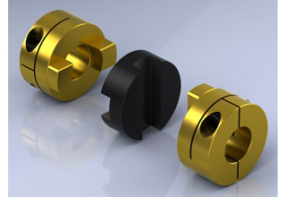
GH Oldham type coupling cross sliding set screw coupling
Description of GH Oldham type coupling cross sliding set screw coupling
>The colloid material is imported PA66, which has good wear resistance, corrosion resistance and electrical insulation
>Sliding design can compensate radial and angular deviation more effectively
>Detachable design, easy to install
>Fastening method of clamping screw
Dimensions of GH Oldham type coupling cross sliding set screw coupling
| model parameter | common bore diameter d1,d2 | ΦD | L | LF | LP | F | M | tightening screw torque (N.M) |
| GH-16X18 | 4,5,6,6.35,7,8 | 16 | 18 | 7.1 | 11.6 | 3.55 | M3 | 0.7 |
| GH-20X25 | 5,6,6.35,7,8,9,9.525 | 20 | 25 | 9.1 | 12.7 | 4.55 | M4 | 1.7 |
| GH-25X28 | 5,6,6.35,8,9,9.525,10,11,12,14 | 25 | 28 | 11.7 | 16.65 | 5.58 | M4 | 1.7 |
| GH-32×33 | 5,6,8,9,9.525,10,11,12,12.7,14,15,16 | 32 | 33 | 14 | 19.5 | 7 | M4 | 1.7 |
| GH-40X35 | 8,9,9.525,10,11,12,12.7,14,14,16,17,18,19,20 | 40 | 35 | 15.5 | 18.4 | 7.75 | M4 | 1.7 |
| GH-45X46 | 8,9,9.525,10,11,12.7,14,15,16,17,18,19,20,22 | 45 | 46 | 21.5 | 18.4 | 9 | M5 | 4 |
| GH-50X38 | 10,12,12.7,14,15,16,17,18,19,20,22,24,25 | 50 | 38 | 16.5 | 15 | 8.25 | M5 | 4 |
| GH-55X57 | 10,12,12.7,14,15,16,17,18,19,20,22,24,25,28,30,32 | 55 | 57 | 27 | 17.5 | 10.5 | M5 | 4 |
| GH-63X47 | 14,15,16,17,18,19,20,22,24,25,28,30,32 | 63 | 47 | 21 | 17.5 | 10.5 | M6 | 8.4 |
| GH-70X77 | 16,17,18,19,20,22,24,25,28,30,32,38,40 | 70 | 77 | 36.5 | 25 | 13.5 | M8 | 10.5 |
| model parameter | Rated torque (N.M)* |
allowable eccentricity (mm)* |
allowable deflection angle (°)* |
allowable axial deviation (mm)* |
maximum speed rpm |
static torsional stiffness (N.M/rad) |
moment of inertia (Kg.M2) |
Material of shaft sleeve | Material of shrapnel | surface treatment | weight (g) |
| GH-16X18 | 0.7 | 0.8 | 3 | ±0.2 | 9000 | 30 | 3.3×10⁻⁷ | High strength aluminum alloy | P A 6 6 | Anodizing treatment | 6 |
| GH-20X25 | 1.2 | 1.2 | 3 | ±0.2 | 7000 | 58 | 1.1×10⁻⁶ | 18 | |||
| GH-25X28 | 2 | 1.6 | 3 | ±0.2 | 6000 | 130 | 3.1×10⁻⁶ | 25 | |||
| GH-32×33 | 4.5 | 2 | 3 | ±0.2 | 4800 | 270 | 9.6×10⁻⁶ | 44 | |||
| GH-40X35 | 9 | 2.4 | 3 | ±0.2 | 3600 | 520 | 2.3×10⁻⁵ | 81 | |||
| GH-45X46 | 12 | 2.8 | 3 | ±0.2 | 3500 | 560 | 3.8×10⁻⁵ | 136 | |||
| GH-50X38 | 19 | 2.6 | 3 | ±0.2 | 3000 | 800 | 1.8×10⁻⁴ | 142 | |||
| GH-55X57 | 22 | 3.3 | 3 | ±0.2 | 2800 | 795 | 8.0×10⁻⁴ | 255 | |||
| GH-63X47 | 19 | 3 | 3 | ±0.2 | 2500 | 1200 | 8.3×10⁻⁴ | 320 | |||
| GH-70X77 | 56 | 3.8 | 3 | ±0.2 | 2500 | 1260 | 3.9×10⁻⁴ | 445 |
How to Identify Signs of Wear or Damage in an Oldham Coupling?
Regular inspection of Oldham couplings is essential to ensure their proper functioning and prevent unexpected failures. Here are some signs of wear or damage to look for during the inspection:
1. Visible Cracks or Deformation: Check the center disc and the hubs for any visible cracks, tears, or deformation. These can be indicators of excessive stress or misalignment.
2. Abnormal Vibrations: Excessive vibrations during operation may suggest that the coupling is not functioning correctly. It could be due to wear in the center disc or improper installation.
3. Unusual Noise: Grinding, clicking, or banging noises during equipment operation may indicate that the Oldham coupling is experiencing excessive backlash or misalignment.
4. Increased Backlash: If there is noticeable play or free movement between the coupling components, it may be a sign of wear in the center disc or worn hubs.
5. Reduced Performance: A decrease in the performance of the machinery or unexpected issues with power transmission could be indicative of coupling problems.
6. Abnormal Heating: If the coupling becomes unusually hot during operation, it may suggest friction or misalignment issues.
7. Excessive Wear on Center Disc: Inspect the center disc for signs of wear, such as grooves, uneven surfaces, or material loss. This may occur over time due to the repeated flexing of the disc.
8. Lubrication Issues: Improper or inadequate lubrication can lead to increased friction and wear in the coupling components.
If any of these signs are observed during the inspection, it is essential to address the issue promptly. Depending on the severity of the wear or damage, the Oldham coupling may require replacement or repair. Regular maintenance and proper lubrication can help extend the life of the coupling and prevent unexpected failures, ensuring smooth and reliable operation in the machinery or equipment.
Real-World Examples of Oldham Coupling Usage in Mechanical Engineering
Oldham couplings are widely used in various mechanical engineering applications due to their ability to transmit torque while compensating for angular misalignment. Here are some real-world examples of Oldham coupling usage:
- Packaging Machinery: Oldham couplings are commonly employed in packaging machines that require precise and continuous motion. These couplings help connect the motor shaft to various components in the packaging process, such as conveyor belts, rollers, and cutting blades.
- Automated Assembly Lines: In automated assembly lines, Oldham couplings are utilized to transfer torque from the motor to the robotic arms or handling mechanisms. The couplings enable smooth and accurate movement, ensuring precise positioning of components during assembly.
- Printing Equipment: Printing machines utilize Oldham couplings to transmit power from the motors to the printing cylinders and rollers. The couplings accommodate any misalignment between the shafts and minimize vibration, resulting in improved print quality.
- Material Handling Systems: Material handling systems, such as conveyor systems, use Oldham couplings to connect drive motors to the conveyor belts. These couplings facilitate the efficient transfer of goods while compensating for any misalignment that may occur during operation.
- Industrial Pumps: Oldham couplings are employed in industrial pumps to transfer power from the motor to the pump impeller. They aid in absorbing vibration and maintaining alignment, which is crucial for the pump’s optimal performance and longevity.
- Medical Devices: Some medical devices, such as scanning equipment and diagnostic machines, incorporate Oldham couplings to ensure precise and reliable motion, contributing to accurate medical imaging and diagnosis.
These examples demonstrate the versatility of Oldham couplings in various mechanical engineering applications. Their ability to handle misalignment, reduce vibration, and transmit torque makes them a valuable component in many industrial sectors.

How an Oldham Coupling Accommodates Misalignment Between Shafts
An Oldham coupling accommodates misalignment between shafts through its unique design, which consists of three main components:
- Two Hubs: Each hub is attached to the shaft of the connected equipment. The hubs have a series of slots around their circumference.
- Middle Block: The middle block fits between the two hubs and has perpendicular slots on its inner diameter. It connects the two hubs while allowing relative movement between them.
When the shafts experience angular or axial misalignment, the middle block slides within the slots of both hubs. The perpendicular slots on the middle block engage with the slots on the hubs, creating a parallelogram linkage.
This parallelogram linkage allows the Oldham coupling to compensate for angular misalignment by enabling the hubs to rotate independently about their own axes. The sliding action of the middle block accommodates axial misalignment by allowing the hubs to move slightly closer or farther apart.
The use of sliding contact instead of direct physical contact between the hubs minimizes friction, backlash, and wear, making the Oldham coupling an efficient and reliable method for transmitting torque while accommodating misalignment.
Overall, the Oldham coupling’s ability to handle both angular and axial misalignment ensures smooth and precise torque transmission between shafts, reducing stress on connected equipment and extending the lifespan of mechanical components.


editor by CX 2023-09-07