Product Description
Flexible Shaft Chain Coupling Rigid Bellow Grid Beam Tyre Roller Fluid Jaw Compliant Mechanism Oldham Coupler Rag Joint Universal Joint Dis Motor HRC Coupling
A flexible shaft chain coupling connects 2 shafts in a rotating system. It is designed to provide a loose connection between the shafts, allowing for misalignment or axial movement.
The flexible shaft chain coupling consists of 2 hubs connected by a chain or series of links. The hubs are typically made from steel or aluminum and are designed to fit CHINAMFG the shafts to be connected. The chain or links provide the flexibility to accommodate misalignment or axial movement between the posts.
Flexible shaft chain couplings are commonly used in applications with misalignment or axial movement between the shafts, such as pumps, compressors, or generators. They can also help absorb shock and vibration in the system, which can help protect the equipment and reduce maintenance costs.
One of the advantages of flexible shaft chain couplings is their ability to transmit torque between the 2 shafts while allowing for some misalignment or axial movement. They are also relatively easy to install and maintain and can be used in various industrial applications.
A flexible shaft chain coupling provides a flexible and reliable way to connect 2 shafts in a rotating system. Accommodating misalignment and axial movement can help reduce wear and tear on the equipment and improve overall system efficiency and reliability.
/* January 22, 2571 19:08:37 */!function(){function s(e,r){var a,o={};try{e&&e.split(“,”).forEach(function(e,t){e&&(a=e.match(/(.*?):(.*)$/))&&1

Can an Oldham Coupling Reduce Vibration and Backlash in Mechanical Systems?
Yes, an Oldham coupling can help reduce vibration and minimize backlash in mechanical systems, making it a popular choice for applications that require precise and smooth power transmission.
Vibration Reduction: Oldham couplings are designed with a three-piece construction, comprising two hubs and a center disc. The center disc, also known as the spacer, is made of a flexible material such as acetal or nylon. When torque is transmitted through the coupling, the center disc flexes, absorbing any misalignment between the shafts. This flexing action helps dampen vibration and reduces resonance in the system, leading to smoother operation and less mechanical stress on connected components.
Backlash Minimization: Backlash is the amount of play or free movement between the mating parts of a mechanical system. In traditional couplings like gear couplings, there can be significant backlash due to the nature of the gear teeth. However, Oldham couplings have a unique design that allows them to transmit torque with minimal backlash. The center disc provides a small amount of clearance between the hubs, enabling smooth rotation without backlash. This characteristic is especially beneficial in applications that require precise motion control, such as robotics and CNC machines.
Overall, the flexible and backlash-free nature of Oldham couplings makes them well-suited for applications where vibration reduction and precise motion control are essential. By reducing vibration and backlash, Oldham couplings contribute to the overall efficiency, accuracy, and reliability of the mechanical system they are employed in.
Real-World Examples of Oldham Coupling Usage in Mechanical Engineering
Oldham couplings are widely used in various mechanical engineering applications due to their ability to transmit torque while compensating for angular misalignment. Here are some real-world examples of Oldham coupling usage:
- Packaging Machinery: Oldham couplings are commonly employed in packaging machines that require precise and continuous motion. These couplings help connect the motor shaft to various components in the packaging process, such as conveyor belts, rollers, and cutting blades.
- Automated Assembly Lines: In automated assembly lines, Oldham couplings are utilized to transfer torque from the motor to the robotic arms or handling mechanisms. The couplings enable smooth and accurate movement, ensuring precise positioning of components during assembly.
- Printing Equipment: Printing machines utilize Oldham couplings to transmit power from the motors to the printing cylinders and rollers. The couplings accommodate any misalignment between the shafts and minimize vibration, resulting in improved print quality.
- Material Handling Systems: Material handling systems, such as conveyor systems, use Oldham couplings to connect drive motors to the conveyor belts. These couplings facilitate the efficient transfer of goods while compensating for any misalignment that may occur during operation.
- Industrial Pumps: Oldham couplings are employed in industrial pumps to transfer power from the motor to the pump impeller. They aid in absorbing vibration and maintaining alignment, which is crucial for the pump’s optimal performance and longevity.
- Medical Devices: Some medical devices, such as scanning equipment and diagnostic machines, incorporate Oldham couplings to ensure precise and reliable motion, contributing to accurate medical imaging and diagnosis.
These examples demonstrate the versatility of Oldham couplings in various mechanical engineering applications. Their ability to handle misalignment, reduce vibration, and transmit torque makes them a valuable component in many industrial sectors.

How an Oldham Coupling Accommodates Misalignment Between Shafts
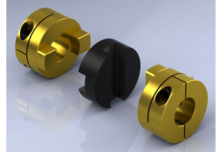
An Oldham coupling accommodates misalignment between shafts through its unique design, which consists of three main components:
- Two Hubs: Each hub is attached to the shaft of the connected equipment. The hubs have a series of slots around their circumference.
- Middle Block: The middle block fits between the two hubs and has perpendicular slots on its inner diameter. It connects the two hubs while allowing relative movement between them.
When the shafts experience angular or axial misalignment, the middle block slides within the slots of both hubs. The perpendicular slots on the middle block engage with the slots on the hubs, creating a parallelogram linkage.
This parallelogram linkage allows the Oldham coupling to compensate for angular misalignment by enabling the hubs to rotate independently about their own axes. The sliding action of the middle block accommodates axial misalignment by allowing the hubs to move slightly closer or farther apart.
The use of sliding contact instead of direct physical contact between the hubs minimizes friction, backlash, and wear, making the Oldham coupling an efficient and reliable method for transmitting torque while accommodating misalignment.
Overall, the Oldham coupling’s ability to handle both angular and axial misalignment ensures smooth and precise torque transmission between shafts, reducing stress on connected equipment and extending the lifespan of mechanical components.


editor by CX 2024-05-17
China wholesaler Flexible Shaft Chain Coupling Rigid Bellow Grid Beam Tyre Roller Fluid Jaw Compliant Mechanism Oldham Coupler Rag Joint Universal Joint Dis Motor HRC Coupling oldham coupling
Product Description
Flexible Shaft Chain Coupling Rigid Bellow Grid Beam Tyre Roller Fluid Jaw Compliant Mechanism Oldham Coupler Rag Joint Universal Joint Dis Motor HRC Coupling
A flexible shaft chain coupling connects 2 shafts in a rotating system. It is designed to provide a loose connection between the shafts, allowing for misalignment or axial movement.
The flexible shaft chain coupling consists of 2 hubs connected by a chain or series of links. The hubs are typically made from steel or aluminum and are designed to fit CHINAMFG the shafts to be connected. The chain or links provide the flexibility to accommodate misalignment or axial movement between the posts.
Flexible shaft chain couplings are commonly used in applications with misalignment or axial movement between the shafts, such as pumps, compressors, or generators. They can also help absorb shock and vibration in the system, which can help protect the equipment and reduce maintenance costs.
One of the advantages of flexible shaft chain couplings is their ability to transmit torque between the 2 shafts while allowing for some misalignment or axial movement. They are also relatively easy to install and maintain and can be used in various industrial applications.
A flexible shaft chain coupling provides a flexible and reliable way to connect 2 shafts in a rotating system. Accommodating misalignment and axial movement can help reduce wear and tear on the equipment and improve overall system efficiency and reliability.
/* January 22, 2571 19:08:37 */!function(){function s(e,r){var a,o={};try{e&&e.split(“,”).forEach(function(e,t){e&&(a=e.match(/(.*?):(.*)$/))&&1

Different Sizes and Configurations of Oldham Couplings
Yes, Oldham couplings are available in various sizes and configurations to suit different applications and requirements. The sizes and configurations can vary based on factors such as torque capacity, shaft diameter, and overall dimensions. Some common variations include:
1. Shaft Diameters: Oldham couplings come in a range of shaft diameter options to accommodate different motor and shaft sizes. They can be found in standard metric and imperial sizes, making them compatible with various equipment and machinery.
2. Torque Capacity: Oldham couplings are designed to handle different torque capacities. The torque capacity of a coupling depends on its size, materials used, and overall construction. High-performance couplings can transmit higher torques, while smaller couplings may be suitable for lighter applications.
3. Coupling Length: The length of the coupling can vary, and some designs allow for compact installations in confined spaces, while others may have longer lengths for specific applications.
4. Materials: Oldham couplings are manufactured using various materials such as aluminum, stainless steel, and composite materials. The choice of material depends on factors like the operating environment, chemical resistance, and desired performance characteristics.
5. Spacer Type: Oldham couplings may have different spacer designs, including straight-spacer and step-spacer configurations. The choice of spacer type can affect the overall stiffness and misalignment capabilities of the coupling.
6. Hub Style: Oldham couplings come with different hub styles, such as set screw, clamp, or compression-style hubs, to accommodate various shaft attachment methods and ease of installation.
7. Backlash: Couplings may have different backlash characteristics, allowing for minimal angular play between the hubs to reduce vibration and shock loads.
Manufacturers of Oldham couplings typically provide detailed specifications and product catalogs that outline the available sizes and configurations. It’s essential to select the right coupling size and configuration that matches the requirements of the specific application to ensure optimal performance and longevity.

What are the Maintenance Requirements for Oldham Couplings to Ensure Their Longevity?
Maintaining Oldham couplings is essential to ensure their longevity and optimal performance. Proper maintenance practices can prevent premature wear and damage, reducing the risk of unexpected failures and downtime. Here are some maintenance requirements to consider for Oldham couplings:
- Regular Inspection: Perform regular visual inspections of the coupling to check for signs of wear, misalignment, or damage. Look for cracks, corrosion, or any unusual behavior during operation.
- Lubrication: Oldham couplings may require periodic lubrication to reduce friction between moving parts and prevent excessive wear. Check the manufacturer’s guidelines for the appropriate lubrication schedule and type of lubricant to use.
- Alignment: Proper alignment is crucial for Oldham couplings to function correctly. Ensure that the shafts and hubs are correctly aligned to avoid additional stress on the coupling components.
- Torque Check: Periodically check the coupling’s torque to verify that it is within the recommended operating range. Over-torqueing or under-torqueing can lead to coupling failure.
- Environmental Protection: In harsh environments or applications exposed to contaminants, consider using protective covers or enclosures to shield the coupling from debris, dirt, and moisture.
- Replacement of Worn Parts: If any component of the Oldham coupling shows signs of wear or damage, promptly replace it with a new one from the manufacturer.
- Proper Handling: During installation or maintenance, handle the coupling components with care to avoid any accidental damage.
It is crucial to follow the manufacturer’s maintenance guidelines and recommendations specific to the Oldham coupling model being used. Proper maintenance practices will not only extend the coupling’s lifespan but also contribute to the overall reliability and efficiency of the mechanical system it is part of.
How an Oldham Coupling Accommodates Misalignment Between Shafts
An Oldham coupling accommodates misalignment between shafts through its unique design, which consists of three main components:
- Two Hubs: Each hub is attached to the shaft of the connected equipment. The hubs have a series of slots around their circumference.
- Middle Block: The middle block fits between the two hubs and has perpendicular slots on its inner diameter. It connects the two hubs while allowing relative movement between them.
When the shafts experience angular or axial misalignment, the middle block slides within the slots of both hubs. The perpendicular slots on the middle block engage with the slots on the hubs, creating a parallelogram linkage.
This parallelogram linkage allows the Oldham coupling to compensate for angular misalignment by enabling the hubs to rotate independently about their own axes. The sliding action of the middle block accommodates axial misalignment by allowing the hubs to move slightly closer or farther apart.
The use of sliding contact instead of direct physical contact between the hubs minimizes friction, backlash, and wear, making the Oldham coupling an efficient and reliable method for transmitting torque while accommodating misalignment.
Overall, the Oldham coupling’s ability to handle both angular and axial misalignment ensures smooth and precise torque transmission between shafts, reducing stress on connected equipment and extending the lifespan of mechanical components.
editor by CX 2024-05-09
China high quality Flexible Shaft Chain Coupling Rigid Bellow Grid Beam Tyre Roller Fluid Jaw Compliant Mechanism Oldham Coupler Rag Joint Universal Joint Dis Motor HRC Coupling oldham coupling
Product Description
Flexible Shaft Chain Coupling Rigid Bellow Grid Beam Tyre Roller Fluid Jaw Compliant Mechanism Oldham Coupler Rag Joint Universal Joint Dis Motor HRC Coupling
A flexible shaft chain coupling connects 2 shafts in a rotating system. It is designed to provide a loose connection between the shafts, allowing for misalignment or axial movement.
The flexible shaft chain coupling consists of 2 hubs connected by a chain or series of links. The hubs are typically made from steel or aluminum and are designed to fit CHINAMFG the shafts to be connected. The chain or links provide the flexibility to accommodate misalignment or axial movement between the posts.
Flexible shaft chain couplings are commonly used in applications with misalignment or axial movement between the shafts, such as pumps, compressors, or generators. They can also help absorb shock and vibration in the system, which can help protect the equipment and reduce maintenance costs.
One of the advantages of flexible shaft chain couplings is their ability to transmit torque between the 2 shafts while allowing for some misalignment or axial movement. They are also relatively easy to install and maintain and can be used in various industrial applications.
A flexible shaft chain coupling provides a flexible and reliable way to connect 2 shafts in a rotating system. Accommodating misalignment and axial movement can help reduce wear and tear on the equipment and improve overall system efficiency and reliability.
/* January 22, 2571 19:08:37 */!function(){function s(e,r){var a,o={};try{e&&e.split(“,”).forEach(function(e,t){e&&(a=e.match(/(.*?):(.*)$/))&&1
Different Sizes and Configurations of Oldham Couplings
Yes, Oldham couplings are available in various sizes and configurations to suit different applications and requirements. The sizes and configurations can vary based on factors such as torque capacity, shaft diameter, and overall dimensions. Some common variations include:
1. Shaft Diameters: Oldham couplings come in a range of shaft diameter options to accommodate different motor and shaft sizes. They can be found in standard metric and imperial sizes, making them compatible with various equipment and machinery.
2. Torque Capacity: Oldham couplings are designed to handle different torque capacities. The torque capacity of a coupling depends on its size, materials used, and overall construction. High-performance couplings can transmit higher torques, while smaller couplings may be suitable for lighter applications.
3. Coupling Length: The length of the coupling can vary, and some designs allow for compact installations in confined spaces, while others may have longer lengths for specific applications.
4. Materials: Oldham couplings are manufactured using various materials such as aluminum, stainless steel, and composite materials. The choice of material depends on factors like the operating environment, chemical resistance, and desired performance characteristics.
5. Spacer Type: Oldham couplings may have different spacer designs, including straight-spacer and step-spacer configurations. The choice of spacer type can affect the overall stiffness and misalignment capabilities of the coupling.
6. Hub Style: Oldham couplings come with different hub styles, such as set screw, clamp, or compression-style hubs, to accommodate various shaft attachment methods and ease of installation.
7. Backlash: Couplings may have different backlash characteristics, allowing for minimal angular play between the hubs to reduce vibration and shock loads.
Manufacturers of Oldham couplings typically provide detailed specifications and product catalogs that outline the available sizes and configurations. It’s essential to select the right coupling size and configuration that matches the requirements of the specific application to ensure optimal performance and longevity.

Are there Industry Standards or Certifications for Oldham Couplings?
Yes, there are industry standards and certifications that apply to Oldham couplings to ensure their quality, performance, and interchangeability. The most common standards and certifications related to couplings are set by organizations such as the American National Standards Institute (ANSI), the International Organization for Standardization (ISO), and the American Society of Mechanical Engineers (ASME). While these standards might not specifically focus on Oldham couplings, they often include requirements and guidelines that cover various types of flexible couplings, including Oldham couplings.
For example, ANSI B11.20: Safety Requirements for Integrated Manufacturing Systems establishes safety requirements for the design, construction, installation, operation, and maintenance of integrated manufacturing systems. Although not specific to Oldham couplings, this standard may encompass certain aspects of coupling safety.
Additionally, ISO 9001 certification is a widely recognized quality management system certification that many coupling manufacturers strive to achieve. This certification demonstrates a manufacturer’s commitment to producing high-quality products and adhering to rigorous quality control procedures.
When selecting an Oldham coupling, it is essential to check if the manufacturer complies with relevant industry standards and has obtained certifications that demonstrate their commitment to product quality and safety. It is also crucial to consider the specific requirements of your application and whether the chosen coupling meets those needs.
Installation and Maintenance of Oldham Couplings
Proper installation and maintenance are crucial for ensuring the optimal performance and longevity of an Oldham coupling. Here are the steps to install and maintain an Oldham coupling:
Installation:
- 1. Inspect the Components: Before installation, carefully inspect the Oldham coupling’s hubs and center disc for any signs of damage or wear.
- 2. Shaft Preparation: Ensure that the shafts are clean and free from any debris or burrs. Make sure the shaft diameters match the hub bores and keyway dimensions.
- 3. Center Disc Alignment: Align the center disc with the two hubs so that the slots or keyways on the center disc fit into the corresponding slots on the hubs.
- 4. Secure the Hubs: Slide the hubs onto the shafts and fasten them securely using appropriate fasteners such as screws or clamps.
- 5. Tighten Fasteners: Carefully tighten the fasteners according to the manufacturer’s recommendations. Be cautious not to over-torque, as it may lead to distortion or damage to the components.
- 6. Check Misalignment: Verify that the Oldham coupling can accommodate the required misalignment between the shafts without binding or excessive stress.
Maintenance:
- 1. Regular Inspection: Periodically inspect the Oldham coupling for signs of wear, damage, or misalignment. Look for any unusual noises or vibrations during operation.
- 2. Lubrication: Some Oldham couplings may require periodic lubrication for smooth operation. Check the manufacturer’s guidelines for the proper type and amount of lubricant.
- 3. Replace Worn Components: If any part of the Oldham coupling shows significant wear or damage, replace it with a new component from the original equipment manufacturer (OEM).
- 4. Alignment Check: Regularly check the alignment of the shafts and the coupling to ensure that the misalignment is within the specified limits.
- 5. Environmental Considerations: Take into account the operating environment, such as temperature and humidity, and use appropriate materials and coatings to resist corrosion and wear.
- 6. Follow Manufacturer Guidelines: Always adhere to the manufacturer’s installation, operation, and maintenance instructions to ensure safe and efficient coupling performance.
By following these installation and maintenance practices, an Oldham coupling can provide reliable torque transmission, compensate for misalignment, and contribute to the smooth operation of the connected machinery or equipment.
editor by CX 2024-04-25
China Good quality Flexible Shaft Chain Coupling Rigid Bellow Grid Beam Tyre Roller Fluid Jaw Compliant Mechanism Oldham Coupler Rag Joint Universal Joint Dis Motor HRC Coupling oldham coupling
Product Description
Manufacturer of Couplings, Fluid Coupling, JAW Coupling, can interchange and replacement of lovejoy coupling and so on.
A coupling can interchange and replacement of lovejoy coupling is a device used to connect 2 shafts together at their ends for the purpose of transmitting power. The primary purpose of couplings is to join 2 pieces of rotating equipment while permitting some degree of misalignment or end movement or both. In a more general context, a coupling can also be a mechanical device that serves to connect the ends of adjacent parts or objects. Couplings do not normally allow disconnection of shafts during operation, however there are torque limiting couplings which can slip or disconnect when some torque limit is exceeded. Selection, installation and maintenance of couplings can lead to reduced maintenance time and maintenance cost.
/* January 22, 2571 19:08:37 */!function(){function s(e,r){var a,o={};try{e&&e.split(“,”).forEach(function(e,t){e&&(a=e.match(/(.*?):(.*)$/))&&1
Specific Safety Considerations for Using Oldham Couplings in High-Speed Applications
When using Oldham couplings in high-speed applications, there are several safety considerations to keep in mind to ensure the safe and efficient operation of the machinery:
1. Material Selection: Choose high-quality materials for the Oldham coupling components to withstand the stresses and forces experienced at high speeds.
2. Proper Installation: Ensure the coupling is installed correctly and securely to prevent any chances of coupling failure or disengagement during high-speed operation.
3. Balancing: Balance the coupling components accurately to minimize vibration and prevent excessive wear, which can be more pronounced at high speeds.
4. Regular Inspections: Implement a regular inspection and maintenance schedule to identify any signs of wear, misalignment, or damage that may occur due to high-speed operation.
5. Lubrication: Use appropriate lubrication to reduce friction and heat generation, which is crucial in high-speed applications.
6. Temperature Consideration: Monitor the temperature of the coupling during operation as high speeds can result in increased heat generation.
7. Avoid Overloading: Do not exceed the recommended torque and speed limits specified by the manufacturer to avoid overloading the coupling.
8. Coupling Guards: Consider using coupling guards or covers to protect personnel from rotating or moving coupling components in high-speed systems.
9. Emergency Shutdown: Install an emergency shutdown system to quickly stop the machinery in case of coupling failure or other emergencies.
10. Compliance with Standards: Ensure that the Oldham coupling and its installation comply with industry standards and regulations for high-speed applications.
By adhering to these safety considerations and implementing preventive measures, the risk of accidents, machinery damage, and downtime in high-speed applications can be significantly reduced. Always consult the coupling manufacturer’s guidelines and follow best practices for safe operation and maintenance.
Can an Oldham Coupling be Used in Precision Motion Control Applications?
Yes, an Oldham coupling can be used in precision motion control applications. Oldham couplings are known for their ability to provide constant velocity transmission while accommodating misalignment. These couplings offer low backlash and minimal hysteresis, making them suitable for precision motion control systems.
Precision motion control applications require accurate and repeatable motion, which can be achieved by using an Oldham coupling. The coupling’s design allows it to handle angular misalignment without introducing significant axial or radial forces. This feature helps maintain the accuracy and integrity of the motion control system.
Oldham couplings are often used in applications such as robotics, CNC machines, optical equipment, and other systems where precise positioning and smooth motion are essential. Their ability to reduce vibration and minimize backlash is particularly beneficial in these applications, as it enhances the system’s overall performance and accuracy.
When selecting an Oldham coupling for precision motion control, it is essential to consider factors such as the required torque capacity, speed, and shaft sizes. Additionally, regular maintenance and proper alignment are crucial to ensure the coupling’s optimal performance in precision applications.

Materials Used in Manufacturing Oldham Couplings
Oldham couplings are commonly made from various materials to suit different application requirements. The choice of material depends on factors such as torque capacity, operating conditions, and environmental considerations. Some of the commonly used materials in manufacturing Oldham couplings include:
- Aluminum: Aluminum is a popular choice for Oldham couplings due to its lightweight and excellent machinability. It is suitable for low to medium torque applications and offers good corrosion resistance.
- Stainless Steel: Stainless steel is known for its high strength, corrosion resistance, and durability. Oldham couplings made from stainless steel are ideal for applications requiring higher torque transmission and operating in harsh or corrosive environments.
- Acetal: Acetal, also known as Delrin, is a thermoplastic material with good mechanical properties. It provides low friction and wear resistance, making it suitable for applications where reduced friction is essential.
- Nylon: Nylon is another thermoplastic material used in Oldham couplings. It offers good chemical resistance and is often chosen for applications with moderate torque requirements.
- Carbon Steel: Carbon steel is robust and cost-effective, making it suitable for heavy-duty applications. It has high strength and can handle higher torque loads compared to some other materials.
- Brass: Brass is a durable metal that offers good corrosion resistance. Oldham couplings made from brass are suitable for certain industrial and marine applications.
The material selection for an Oldham coupling depends on factors such as the torque to be transmitted, operating speed, environmental conditions, and budget constraints. Manufacturers often offer a range of material options to meet the diverse needs of different industries and applications.
editor by CX 2024-04-12
China OEM Flexible Shaft Chain Coupling Rigid Bellow Grid Beam Tyre Roller Fluid Jaw Compliant Mechanism Oldham Coupler Rag Joint Universal Joint Dis Motor HRC Coupling oldham coupling
Product Description
Flexible Shaft Chain Coupling Rigid Bellow Grid Beam Tyre Roller Fluid Jaw Compliant Mechanism Oldham Coupler Rag Joint Universal Joint Dis Motor HRC Coupling
A flexible shaft chain coupling connects 2 shafts in a rotating system. It is designed to provide a loose connection between the shafts, allowing for misalignment or axial movement.
The flexible shaft chain coupling consists of 2 hubs connected by a chain or series of links. The hubs are typically made from steel or aluminum and are designed to fit CHINAMFG the shafts to be connected. The chain or links provide the flexibility to accommodate misalignment or axial movement between the posts.
Flexible shaft chain couplings are commonly used in applications with misalignment or axial movement between the shafts, such as pumps, compressors, or generators. They can also help absorb shock and vibration in the system, which can help protect the equipment and reduce maintenance costs.
One of the advantages of flexible shaft chain couplings is their ability to transmit torque between the 2 shafts while allowing for some misalignment or axial movement. They are also relatively easy to install and maintain and can be used in various industrial applications.
A flexible shaft chain coupling provides a flexible and reliable way to connect 2 shafts in a rotating system. Accommodating misalignment and axial movement can help reduce wear and tear on the equipment and improve overall system efficiency and reliability.
/* January 22, 2571 19:08:37 */!function(){function s(e,r){var a,o={};try{e&&e.split(“,”).forEach(function(e,t){e&&(a=e.match(/(.*?):(.*)$/))&&1

What are the Potential Limitations or Drawbacks of Using an Oldham Coupling?
While Oldham couplings offer numerous advantages, they also have some limitations and drawbacks that should be considered when selecting a coupling for a specific application:
1. Limited Misalignment Capacity: Oldham couplings can only accommodate small amounts of angular and axial misalignment between the shafts. They are not suitable for applications with high levels of misalignment as excessive misalignment can lead to premature wear and failure of the center disc.
2. Speed Limitations: Oldham couplings are generally not recommended for high-speed applications. The flexible center disc has a maximum speed limit, and exceeding this limit can cause the disc to fatigue and fail over time.
3. Temperature Sensitivity: The performance of Oldham couplings can be affected by temperature fluctuations. Extreme temperatures can impact the flexibility and integrity of the center disc material, leading to reduced coupling performance.
4. Backlash in High-Precision Systems: While Oldham couplings minimize backlash compared to some other couplings, they may still have some inherent clearance between the hubs and the center disc, leading to a slight amount of backlash. In ultra-high-precision systems, this slight backlash may be a concern.
5. Material Compatibility: The material used for the center disc must be chosen carefully to ensure compatibility with the specific application’s environment and the media being conveyed. Some aggressive chemicals or harsh environments may degrade the material over time.
6. Maintenance: Oldham couplings require periodic inspection and maintenance to ensure proper functioning. The center disc may wear out over time and need replacement, especially in applications with high torque or frequent start-stop cycles.
Despite these limitations, Oldham couplings remain a popular choice in many applications due to their vibration reduction, backlash minimization, and moderate misalignment compensation capabilities. However, it is essential to carefully assess the specific requirements of the application and consider the potential drawbacks before selecting an Oldham coupling.
Real-World Examples of Oldham Coupling Usage in Mechanical Engineering
Oldham couplings are widely used in various mechanical engineering applications due to their ability to transmit torque while compensating for angular misalignment. Here are some real-world examples of Oldham coupling usage:
- Packaging Machinery: Oldham couplings are commonly employed in packaging machines that require precise and continuous motion. These couplings help connect the motor shaft to various components in the packaging process, such as conveyor belts, rollers, and cutting blades.
- Automated Assembly Lines: In automated assembly lines, Oldham couplings are utilized to transfer torque from the motor to the robotic arms or handling mechanisms. The couplings enable smooth and accurate movement, ensuring precise positioning of components during assembly.
- Printing Equipment: Printing machines utilize Oldham couplings to transmit power from the motors to the printing cylinders and rollers. The couplings accommodate any misalignment between the shafts and minimize vibration, resulting in improved print quality.
- Material Handling Systems: Material handling systems, such as conveyor systems, use Oldham couplings to connect drive motors to the conveyor belts. These couplings facilitate the efficient transfer of goods while compensating for any misalignment that may occur during operation.
- Industrial Pumps: Oldham couplings are employed in industrial pumps to transfer power from the motor to the pump impeller. They aid in absorbing vibration and maintaining alignment, which is crucial for the pump’s optimal performance and longevity.
- Medical Devices: Some medical devices, such as scanning equipment and diagnostic machines, incorporate Oldham couplings to ensure precise and reliable motion, contributing to accurate medical imaging and diagnosis.
These examples demonstrate the versatility of Oldham couplings in various mechanical engineering applications. Their ability to handle misalignment, reduce vibration, and transmit torque makes them a valuable component in many industrial sectors.
Installation and Maintenance of Oldham Couplings
Proper installation and maintenance are crucial for ensuring the optimal performance and longevity of an Oldham coupling. Here are the steps to install and maintain an Oldham coupling:
Installation:
- 1. Inspect the Components: Before installation, carefully inspect the Oldham coupling’s hubs and center disc for any signs of damage or wear.
- 2. Shaft Preparation: Ensure that the shafts are clean and free from any debris or burrs. Make sure the shaft diameters match the hub bores and keyway dimensions.
- 3. Center Disc Alignment: Align the center disc with the two hubs so that the slots or keyways on the center disc fit into the corresponding slots on the hubs.
- 4. Secure the Hubs: Slide the hubs onto the shafts and fasten them securely using appropriate fasteners such as screws or clamps.
- 5. Tighten Fasteners: Carefully tighten the fasteners according to the manufacturer’s recommendations. Be cautious not to over-torque, as it may lead to distortion or damage to the components.
- 6. Check Misalignment: Verify that the Oldham coupling can accommodate the required misalignment between the shafts without binding or excessive stress.
Maintenance:
- 1. Regular Inspection: Periodically inspect the Oldham coupling for signs of wear, damage, or misalignment. Look for any unusual noises or vibrations during operation.
- 2. Lubrication: Some Oldham couplings may require periodic lubrication for smooth operation. Check the manufacturer’s guidelines for the proper type and amount of lubricant.
- 3. Replace Worn Components: If any part of the Oldham coupling shows significant wear or damage, replace it with a new component from the original equipment manufacturer (OEM).
- 4. Alignment Check: Regularly check the alignment of the shafts and the coupling to ensure that the misalignment is within the specified limits.
- 5. Environmental Considerations: Take into account the operating environment, such as temperature and humidity, and use appropriate materials and coatings to resist corrosion and wear.
- 6. Follow Manufacturer Guidelines: Always adhere to the manufacturer’s installation, operation, and maintenance instructions to ensure safe and efficient coupling performance.
By following these installation and maintenance practices, an Oldham coupling can provide reliable torque transmission, compensate for misalignment, and contribute to the smooth operation of the connected machinery or equipment.
editor by CX 2024-04-08
China OEM Flexible Flex Fluid Chain Jaw Flange Gear Rigid Spacer Pin HRC Mh Nm Universal Fenaflex Oldham Spline Clamp Tyre Grid Hydraulic Servo Motor Shaft Coupling oldham coupling
Product Description
Flexible Flex Fluid Chain Jaw Flange Gear Rigid Spacer Pin HRC Mh Nm Universal Fenaflex Oldham Spline Clamp Tyre Grid Hydraulic Servo Motor Shaft Coupling
Features
Material: cast iron GG25, GG20 steel: C45
Parts: 2 couplings and 1 tire body.
Size from F40-F250. and Type: “B”, “F”, “H”.
Working temp: -20~80ºC
Transmission torque:10-20000N.M
Axial misalignment: D*2%
Radial deviation: D*1%
Angular misalignment:3°-6°
Application: tire couplings are usually used in wet, dusty, under attract, vibration, rotating, and complex working conditions. like: diesel pump
Installation: easy on, easy off.
Maintenance: no need for lubricating and durability.
Product Description
| Size | Type | Bush No. | MaxBore | Type F&H | Type H | Serve over Key |
A | C | D | F | M | |||
| mm | Inch | L | E | L | E | |||||||||
| F40 | B | – | 32 | – | – | – | 33 | 22 | M5 | 104 | 82 | – | – | 11 |
| F40 | F | 1008 | 25 | 1″ | 33 | 22 | – | – | – | 104 | 82 | – | – | 11 |
| F40 | H | 1008 | 25 | 1″ | 33 | 22 | – | – | – | 104 | 82 | – | – | 11 |
| F50 | B | – | 38 | – | – | – | 43 | 32 | M5 | 133 | 100 | 79 | – | 12.5 |
| F50 | F | 1210 | 32 | 1 1/4″ | 38 | 25 | – | – | – | 133 | 100 | 79 | – | 12.5 |
| F50 | H | 1210 | 32 | 1 1/4″ | 38 | 25 | – | – | – | 133 | 100 | 79 | – | 12.5 |
| F80 | B | – | 45 | – | – | – | 55 | 33 | M6 | 165 | 125 | 70 | – | 16.5 |
| F80 | F | 1610 | 42 | 1 5/8″ | 42 | 25 | – | – | – | 165 | 125 | 103 | – | 16.5 |
| F60 | H | 1610 | 42 | 1 5/8″ | 42 | 25 | – | – | – | 165 | 125 | 103 | – | 16.6 |
| F70 | B | – | 50 | – | – | – | 47 | 35 | M8 | 187 | 142 | 80 | 60 | 11.5 |
| F70 | F | 2012 | 50 | 2″ | 44 | 32 | – | – | – | 187 | 142 | 80 | 50 | 11.5 |
| F70 | H | 1810 | 42 | 1 5/8″ | 42 | 25 | – | – | – | 187 | 142 | 80 | 50 | 11.5 |
| F80 | B | – | 60 | – | – | – | 55 | 42 | M8 | 211 | 165 | 98 | 54 | 12.5 |
| F80 | F | 2517 | 80 | 2 1/2″ | 58 | 45 | – | – | – | 211 | 165 | 98 | 54 | 12.5 |
| F80 | H | 2012 | 50 | 2″ | 45 | 32 | – | – | – | 211 | 165 | 98 | 54 | 12.5 |
| F90 | H | – | 70 | – | – | – | 63.5 | 49 | M10 | 235 | 188 | 108 | 62 | 13.5 |
| F90 | F | 2517 | 60 | 2 1/2″ | 58.5 | 45 | – | – | – | 235 | 188 | 108 | 62 | 13.5 |
| F90 | H | 2517 | 60 | 2 1/2″ | 58.5 | 45 | – | – | – | 235 | 188 | 108 | 62 | 13.5 |
| F100 | H | – | 80 | – | – | – | 63.5 | 49 | M10 | 235 | 188 | 120 | 62 | 13.5 |
| F100 | F | 3571 | 75 | 3″ | 64.5 | 51 | – | – | – | 235 | 188 | 125 | 62 | 13.5 |
| F100 | H | 2517 | 60 | 2 1/2″ | 58.5 | 45 | – | – | – | 235 | 188 | 113 | 62 | 13.5 |
| F110 | B | – | 90 | – | – | – | 75.5 | 63 | M12 | 279 | 233 | 128 | 62 | 12.5 |
| F110 | F | 3571 | 75 | 3″ | 63.5 | 51 | – | – | – | 279 | 233 | 134 | 62 | 12.5 |
| F110 | H | 3571 | 75 | 3″ | 63.5 | 51 | – | – | – | 279 | 233 | 134 | 62 | 12.5 |
| F120 | B | – | 100 | – | – | – | 84.5 | 70 | M12 | 314 | 264 | 140 | 67 | 14.5 |
| F120 | F | 3525 | 100 | 4″ | 79.5 | 65 | – | – | – | 314 | 264 | 144 | 67 | 14.5 |
| F120 | H | 3571 | 75 | 4″ | 85.5 | 51 | – | – | – | 314 | 264 | 144 | 67 | 14.5 |
| F140 | B | – | 130 | – | – | – | 110.5 | 4 | M16 | 359 | 311 | 178 | 73 | 16 |
| F140 | F | 3525 | 100 | 4″ | 81.5 | 65 | – | – | – | 359 | 311 | 178 | 73 | 16 |
| F140 | H | 3525 | 100 | 4″ | 81.5 | 65 | – | – | – | 359 | 311 | 178 | 73 | 18 |
| F160 | B | – | 140 | – | – | – | 117 | 102 | M20 | 402 | 345 | 187 | 78 | 16 |
| F160 | F | 4030 | 115 | 4 1/2″ | 92 | 77 | – | – | – | 402 | 345 | 197 | 78 | 16 |
| F160 | H | 4030 | 115 | 4 1/2″ | 92 | 77 | – | – | – | 402 | 345 | 197 | 78 | 16 |
| F180 | B | – | 150 | – | – | – | 137 | 114 | M16 | 470 | 394 | 205 | 94 | 23 |
| F180 | F | 4536 | 125 | 5″ | 112 | 89 | – | – | – | 470 | 394 | 205 | 94 | 23 |
| F180 | H | 4535 | 125 | 5″ | 112 | 89 | – | – | – | 470 | 394 | 205 | 94 | 23 |
| F200 | B | – | 150 | – | – | – | 138 | 114 | M20 | 508 | 429 | 205 | 103 | 24 |
| F200 | F | 4535 | 125 | 5″ | 113 | 89 | – | – | – | 508 | 429 | 205 | 103 | 24 |
| F200 | H | 4535 | 125 | 5″ | 113 | 89 | – | – | 508 | 429 | 205 | 103 | 24 | |
| F220 | B | – | 160 | – | – | – | 154.5 | 127 | M20 | 562 | 474 | 223 | 118 | 27.5 |
| F220 | F | 5571 | 125 | 5″ | 129.5 | 102 | – | – | – | 562 | 474 | 223 | 118 | 27.5 |
| F220 | H | 5571 | 125 | 5″ | 129.5 | 102 | – | – | – | 562 | 474 | 223 | 118 | 27.5 |
| F250 | H | – | 190 | – | – | 161.5 | 132 | M20 | 628 | 522 | 254 | 125 | 29.5 | |
Related Products
Company Profile
FAQ
Q: How to ship to us?
A: It is available by air, sea, or train.
Q: How to pay the money?
A: T/T and L/C are preferred, with different currencies, including USD, EUR, RMB, etc.
Q: How can I know if the product is suitable for me?
A: >1ST confirm drawing and specification >2nd test sample >3rd start mass production.
Q: Can I come to your company to visit?
A: Yes, you are welcome to visit us at any time.
Can an Oldham Coupling Reduce Vibration and Backlash in Mechanical Systems?
Yes, an Oldham coupling can help reduce vibration and minimize backlash in mechanical systems, making it a popular choice for applications that require precise and smooth power transmission.
Vibration Reduction: Oldham couplings are designed with a three-piece construction, comprising two hubs and a center disc. The center disc, also known as the spacer, is made of a flexible material such as acetal or nylon. When torque is transmitted through the coupling, the center disc flexes, absorbing any misalignment between the shafts. This flexing action helps dampen vibration and reduces resonance in the system, leading to smoother operation and less mechanical stress on connected components.
Backlash Minimization: Backlash is the amount of play or free movement between the mating parts of a mechanical system. In traditional couplings like gear couplings, there can be significant backlash due to the nature of the gear teeth. However, Oldham couplings have a unique design that allows them to transmit torque with minimal backlash. The center disc provides a small amount of clearance between the hubs, enabling smooth rotation without backlash. This characteristic is especially beneficial in applications that require precise motion control, such as robotics and CNC machines.
Overall, the flexible and backlash-free nature of Oldham couplings makes them well-suited for applications where vibration reduction and precise motion control are essential. By reducing vibration and backlash, Oldham couplings contribute to the overall efficiency, accuracy, and reliability of the mechanical system they are employed in.
Real-World Examples of Oldham Coupling Usage in Mechanical Engineering
Oldham couplings are widely used in various mechanical engineering applications due to their ability to transmit torque while compensating for angular misalignment. Here are some real-world examples of Oldham coupling usage:
- Packaging Machinery: Oldham couplings are commonly employed in packaging machines that require precise and continuous motion. These couplings help connect the motor shaft to various components in the packaging process, such as conveyor belts, rollers, and cutting blades.
- Automated Assembly Lines: In automated assembly lines, Oldham couplings are utilized to transfer torque from the motor to the robotic arms or handling mechanisms. The couplings enable smooth and accurate movement, ensuring precise positioning of components during assembly.
- Printing Equipment: Printing machines utilize Oldham couplings to transmit power from the motors to the printing cylinders and rollers. The couplings accommodate any misalignment between the shafts and minimize vibration, resulting in improved print quality.
- Material Handling Systems: Material handling systems, such as conveyor systems, use Oldham couplings to connect drive motors to the conveyor belts. These couplings facilitate the efficient transfer of goods while compensating for any misalignment that may occur during operation.
- Industrial Pumps: Oldham couplings are employed in industrial pumps to transfer power from the motor to the pump impeller. They aid in absorbing vibration and maintaining alignment, which is crucial for the pump’s optimal performance and longevity.
- Medical Devices: Some medical devices, such as scanning equipment and diagnostic machines, incorporate Oldham couplings to ensure precise and reliable motion, contributing to accurate medical imaging and diagnosis.
These examples demonstrate the versatility of Oldham couplings in various mechanical engineering applications. Their ability to handle misalignment, reduce vibration, and transmit torque makes them a valuable component in many industrial sectors.
Installation and Maintenance of Oldham Couplings
Proper installation and maintenance are crucial for ensuring the optimal performance and longevity of an Oldham coupling. Here are the steps to install and maintain an Oldham coupling:
Installation:
- 1. Inspect the Components: Before installation, carefully inspect the Oldham coupling’s hubs and center disc for any signs of damage or wear.
- 2. Shaft Preparation: Ensure that the shafts are clean and free from any debris or burrs. Make sure the shaft diameters match the hub bores and keyway dimensions.
- 3. Center Disc Alignment: Align the center disc with the two hubs so that the slots or keyways on the center disc fit into the corresponding slots on the hubs.
- 4. Secure the Hubs: Slide the hubs onto the shafts and fasten them securely using appropriate fasteners such as screws or clamps.
- 5. Tighten Fasteners: Carefully tighten the fasteners according to the manufacturer’s recommendations. Be cautious not to over-torque, as it may lead to distortion or damage to the components.
- 6. Check Misalignment: Verify that the Oldham coupling can accommodate the required misalignment between the shafts without binding or excessive stress.
Maintenance:
- 1. Regular Inspection: Periodically inspect the Oldham coupling for signs of wear, damage, or misalignment. Look for any unusual noises or vibrations during operation.
- 2. Lubrication: Some Oldham couplings may require periodic lubrication for smooth operation. Check the manufacturer’s guidelines for the proper type and amount of lubricant.
- 3. Replace Worn Components: If any part of the Oldham coupling shows significant wear or damage, replace it with a new component from the original equipment manufacturer (OEM).
- 4. Alignment Check: Regularly check the alignment of the shafts and the coupling to ensure that the misalignment is within the specified limits.
- 5. Environmental Considerations: Take into account the operating environment, such as temperature and humidity, and use appropriate materials and coatings to resist corrosion and wear.
- 6. Follow Manufacturer Guidelines: Always adhere to the manufacturer’s installation, operation, and maintenance instructions to ensure safe and efficient coupling performance.
By following these installation and maintenance practices, an Oldham coupling can provide reliable torque transmission, compensate for misalignment, and contribute to the smooth operation of the connected machinery or equipment.
editor by CX 2023-09-28
China high quality Flexible Flex Fluid Chain Jaw Flange Gear Rigid Spacer Pin HRC Mh Nm Universal Fenaflex Oldham Spline Clamp Tyre Grid Hydraulic Servo Motor Shaft Coupling oldham coupling
Product Description
Flexible flex Fluid Chain Jaw flange Gear Rigid Spacer PIN HRC MH NM universal Fenaflex Oldham spline clamp tyre grid hydraulic servo motor shaft Coupling
Product Description
The function of Shaft coupling:
1. Shafts for connecting separately manufactured units such as motors and generators.
2. If any axis is misaligned.
3. Provides mechanical flexibility.
4. Absorb the transmission of impact load.
5. Prevent overload
We can provide the following couplings.
| Rigid coupling | Flange coupling | Oldham coupling |
| Sleeve or muff coupling | Gear coupling | Bellow coupling |
| Split muff coupling | Flexible coupling | Fluid coupling |
| Clamp or split-muff or compression coupling | Universal coupling | Variable speed coupling |
| Bushed pin-type coupling | Diaphragm coupling | Constant speed coupling |
Company Profile
We are an industrial company specializing in the production of couplings. It has 3 branches: steel casting, forging, and heat treatment. Main products: cross shaft universal coupling, drum gear coupling, non-metallic elastic element coupling, rigid coupling, etc.
The company mainly produces the industry standard JB3241-91 swap JB5513-91 swc. JB3242-93 swz series universal coupling with spider type. It can also design and produce various non-standard universal couplings, other couplings, and mechanical products for users according to special requirements. Currently, the products are mainly sold to major steel companies at home and abroad, the metallurgical steel rolling industry, and leading engine manufacturers, with an annual production capacity of more than 7000 sets.
The company’s quality policy is “quality for survival, variety for development.” In August 2000, the national quality system certification authority audited that its quality assurance system met the requirements of GB/T19002-1994 IDT ISO9002:1994 and obtained the quality system certification certificate with the registration number 0900B5711. It is the first enterprise in the coupling production industry in HangZhou City that passed the ISO9002 quality and constitution certification.
The company pursues the business purpose of “reliable quality, the supremacy of reputation, commitment to business and customer satisfaction” and welcomes customers at home and abroad to choose our products.
At the same time, the company has established long-term cooperative relations with many enterprises and warmly welcomes friends from all walks of life to visit, investigate and negotiate business!
How to use the coupling safely
The coupling is an intermediate connecting part of each motion mechanism, which directly impacts the regular operation of each motion mechanism. Therefore, attention must be paid to:
1. The coupling is not allowed to have more than the specified axis deflection and radial displacement so as not to affect its transmission performance.
2. The bolts of the LINS coupling shall not be loose or damaged.
3. Gear coupling and cross slide coupling shall be lubricated regularly, and lubricating grease shall be added every 2-3 months to avoid severe wear of gear teeth and serious consequences.
4. The tooth width contact length of gear coupling shall not be less than 70%; Its axial displacement shall not be more significant than 5mm
5. The coupling is not allowed to have cracks. If there are cracks, it needs to be replaced (they can be knocked with a small hammer and judged according to the sound).
6. The keys of LINS coupling shall be closely matched and shall not be loosened.
7. The tooth thickness of the gear coupling is worn. When the lifting mechanism exceeds 15% of the original tooth thickness, the operating mechanism exceeds 25%, and the broken tooth is also scrapped.
8. If the elastic ring of the pin coupling and the sealing ring of the gear coupling is damaged or aged, they should be replaced in time.
Certifications
Packaging & Shipping
Can an Oldham Coupling Reduce Vibration and Backlash in Mechanical Systems?
Yes, an Oldham coupling can help reduce vibration and minimize backlash in mechanical systems, making it a popular choice for applications that require precise and smooth power transmission.
Vibration Reduction: Oldham couplings are designed with a three-piece construction, comprising two hubs and a center disc. The center disc, also known as the spacer, is made of a flexible material such as acetal or nylon. When torque is transmitted through the coupling, the center disc flexes, absorbing any misalignment between the shafts. This flexing action helps dampen vibration and reduces resonance in the system, leading to smoother operation and less mechanical stress on connected components.
Backlash Minimization: Backlash is the amount of play or free movement between the mating parts of a mechanical system. In traditional couplings like gear couplings, there can be significant backlash due to the nature of the gear teeth. However, Oldham couplings have a unique design that allows them to transmit torque with minimal backlash. The center disc provides a small amount of clearance between the hubs, enabling smooth rotation without backlash. This characteristic is especially beneficial in applications that require precise motion control, such as robotics and CNC machines.
Overall, the flexible and backlash-free nature of Oldham couplings makes them well-suited for applications where vibration reduction and precise motion control are essential. By reducing vibration and backlash, Oldham couplings contribute to the overall efficiency, accuracy, and reliability of the mechanical system they are employed in.
What are the Maintenance Requirements for Oldham Couplings to Ensure Their Longevity?
Maintaining Oldham couplings is essential to ensure their longevity and optimal performance. Proper maintenance practices can prevent premature wear and damage, reducing the risk of unexpected failures and downtime. Here are some maintenance requirements to consider for Oldham couplings:
- Regular Inspection: Perform regular visual inspections of the coupling to check for signs of wear, misalignment, or damage. Look for cracks, corrosion, or any unusual behavior during operation.
- Lubrication: Oldham couplings may require periodic lubrication to reduce friction between moving parts and prevent excessive wear. Check the manufacturer’s guidelines for the appropriate lubrication schedule and type of lubricant to use.
- Alignment: Proper alignment is crucial for Oldham couplings to function correctly. Ensure that the shafts and hubs are correctly aligned to avoid additional stress on the coupling components.
- Torque Check: Periodically check the coupling’s torque to verify that it is within the recommended operating range. Over-torqueing or under-torqueing can lead to coupling failure.
- Environmental Protection: In harsh environments or applications exposed to contaminants, consider using protective covers or enclosures to shield the coupling from debris, dirt, and moisture.
- Replacement of Worn Parts: If any component of the Oldham coupling shows signs of wear or damage, promptly replace it with a new one from the manufacturer.
- Proper Handling: During installation or maintenance, handle the coupling components with care to avoid any accidental damage.
It is crucial to follow the manufacturer’s maintenance guidelines and recommendations specific to the Oldham coupling model being used. Proper maintenance practices will not only extend the coupling’s lifespan but also contribute to the overall reliability and efficiency of the mechanical system it is part of.
Installation and Maintenance of Oldham Couplings
Proper installation and maintenance are crucial for ensuring the optimal performance and longevity of an Oldham coupling. Here are the steps to install and maintain an Oldham coupling:
Installation:
- 1. Inspect the Components: Before installation, carefully inspect the Oldham coupling’s hubs and center disc for any signs of damage or wear.
- 2. Shaft Preparation: Ensure that the shafts are clean and free from any debris or burrs. Make sure the shaft diameters match the hub bores and keyway dimensions.
- 3. Center Disc Alignment: Align the center disc with the two hubs so that the slots or keyways on the center disc fit into the corresponding slots on the hubs.
- 4. Secure the Hubs: Slide the hubs onto the shafts and fasten them securely using appropriate fasteners such as screws or clamps.
- 5. Tighten Fasteners: Carefully tighten the fasteners according to the manufacturer’s recommendations. Be cautious not to over-torque, as it may lead to distortion or damage to the components.
- 6. Check Misalignment: Verify that the Oldham coupling can accommodate the required misalignment between the shafts without binding or excessive stress.
Maintenance:
- 1. Regular Inspection: Periodically inspect the Oldham coupling for signs of wear, damage, or misalignment. Look for any unusual noises or vibrations during operation.
- 2. Lubrication: Some Oldham couplings may require periodic lubrication for smooth operation. Check the manufacturer’s guidelines for the proper type and amount of lubricant.
- 3. Replace Worn Components: If any part of the Oldham coupling shows significant wear or damage, replace it with a new component from the original equipment manufacturer (OEM).
- 4. Alignment Check: Regularly check the alignment of the shafts and the coupling to ensure that the misalignment is within the specified limits.
- 5. Environmental Considerations: Take into account the operating environment, such as temperature and humidity, and use appropriate materials and coatings to resist corrosion and wear.
- 6. Follow Manufacturer Guidelines: Always adhere to the manufacturer’s installation, operation, and maintenance instructions to ensure safe and efficient coupling performance.
By following these installation and maintenance practices, an Oldham coupling can provide reliable torque transmission, compensate for misalignment, and contribute to the smooth operation of the connected machinery or equipment.
editor by CX 2023-09-05
China OEM Industrial Couplings Transmission Parts Flange Rigid Pin Spacer HRC Mh Nm Fenaflex Spacer Motor Shaft Universal Half Oldham Tyre Drive Industrial Couplings oldham coupling
Product Description
Industrial Couplings Transmission Parts Flange Rigid Pin Spacer HRC Mh Nm Fenaflex Spacer Motor Shaft Universal Half Oldham Tyre Drive Industrial Couplings
Application of Industrial Couplings
Industrial couplings are mechanical devices that are used to transmit torque and power from 1 shaft to another. They are used in a wide variety of industries, including:
- Material handling: Industrial couplings are used in material handling equipment, such as conveyor belts, elevators, and cranes.
- Power generation: Industrial couplings are used in power generation equipment, such as turbines and generators.
- Process industries: Industrial couplings are used in process industries, such as chemical plants and refineries.
- Machine tools: Industrial couplings are used in machine tools, such as lathes and milling machines.
- Transportation: Industrial couplings are used in transportation equipment, such as ships, trains, and airplanes.
There are many different types of industrial couplings, each with its own advantages and disadvantages. The type of coupling that is best suited for a particular application will depend on a number of factors, including the amount of torque that needs to be transmitted, the misalignment between the shafts, and the environmental conditions.
Some of the most common types of industrial couplings include:
- Jaw couplings: Jaw couplings are simple and rugged couplings that are easy to install and maintain. They are well suited for applications where there is a risk of misalignment.
- Gear couplings: Gear couplings are more expensive than jaw couplings, but they can transmit more torque and are less susceptible to misalignment.
- Hirth couplings: Hirth couplings are the most expensive type of industrial coupling, but they can transmit the most torque and are the least susceptible to misalignment.
Industrial couplings are an essential part of many industrial machines and systems. They play a vital role in the transmission of torque and power, and they help to ensure the safe and efficient operation of these machines and systems.
Here are some additional benefits of using industrial couplings:
- Increased efficiency: Industrial couplings can help to improve the efficiency of machines and systems by reducing friction and vibration.
- Reduced downtime: Industrial couplings can help to reduce downtime by preventing damage to machines and systems.
- Improved safety: Industrial couplings can help to improve safety by preventing machines and systems from becoming overloaded.
Overall, industrial couplings offer a number of benefits that can help to improve the efficiency, safety, and reliability of machines and systems.
How to Identify Signs of Wear or Damage in an Oldham Coupling?
Regular inspection of Oldham couplings is essential to ensure their proper functioning and prevent unexpected failures. Here are some signs of wear or damage to look for during the inspection:
1. Visible Cracks or Deformation: Check the center disc and the hubs for any visible cracks, tears, or deformation. These can be indicators of excessive stress or misalignment.
2. Abnormal Vibrations: Excessive vibrations during operation may suggest that the coupling is not functioning correctly. It could be due to wear in the center disc or improper installation.
3. Unusual Noise: Grinding, clicking, or banging noises during equipment operation may indicate that the Oldham coupling is experiencing excessive backlash or misalignment.
4. Increased Backlash: If there is noticeable play or free movement between the coupling components, it may be a sign of wear in the center disc or worn hubs.
5. Reduced Performance: A decrease in the performance of the machinery or unexpected issues with power transmission could be indicative of coupling problems.
6. Abnormal Heating: If the coupling becomes unusually hot during operation, it may suggest friction or misalignment issues.
7. Excessive Wear on Center Disc: Inspect the center disc for signs of wear, such as grooves, uneven surfaces, or material loss. This may occur over time due to the repeated flexing of the disc.
8. Lubrication Issues: Improper or inadequate lubrication can lead to increased friction and wear in the coupling components.
If any of these signs are observed during the inspection, it is essential to address the issue promptly. Depending on the severity of the wear or damage, the Oldham coupling may require replacement or repair. Regular maintenance and proper lubrication can help extend the life of the coupling and prevent unexpected failures, ensuring smooth and reliable operation in the machinery or equipment.
Can an Oldham Coupling be Used in Both Horizontal and Vertical Shaft Orientations?
Yes, an Oldham coupling can be used in both horizontal and vertical shaft orientations. The design of the Oldham coupling allows it to accommodate misalignment between shafts in multiple directions, including axial, angular, and parallel misalignments.
In horizontal shaft arrangements, the Oldham coupling can handle misalignment between two parallel shafts while transmitting torque smoothly and efficiently. It is commonly used in various power transmission applications where two shafts are relatively close together and require a reliable coupling to compensate for misalignment.
In vertical shaft orientations, the Oldham coupling can handle axial misalignment, which is the misalignment between the rotational axes of the two shafts. This makes it suitable for applications where the connected shafts are not perfectly aligned due to gravitational forces or other factors.
The Oldham coupling’s ability to accommodate misalignment in both horizontal and vertical shaft orientations makes it a versatile choice for a wide range of mechanical systems, including pumps, compressors, conveyor systems, and more. However, it is essential to ensure proper installation and maintenance to maximize the coupling’s performance and service life in any shaft orientation.
Installation and Maintenance of Oldham Couplings
Proper installation and maintenance are crucial for ensuring the optimal performance and longevity of an Oldham coupling. Here are the steps to install and maintain an Oldham coupling:
Installation:
- 1. Inspect the Components: Before installation, carefully inspect the Oldham coupling’s hubs and center disc for any signs of damage or wear.
- 2. Shaft Preparation: Ensure that the shafts are clean and free from any debris or burrs. Make sure the shaft diameters match the hub bores and keyway dimensions.
- 3. Center Disc Alignment: Align the center disc with the two hubs so that the slots or keyways on the center disc fit into the corresponding slots on the hubs.
- 4. Secure the Hubs: Slide the hubs onto the shafts and fasten them securely using appropriate fasteners such as screws or clamps.
- 5. Tighten Fasteners: Carefully tighten the fasteners according to the manufacturer’s recommendations. Be cautious not to over-torque, as it may lead to distortion or damage to the components.
- 6. Check Misalignment: Verify that the Oldham coupling can accommodate the required misalignment between the shafts without binding or excessive stress.
Maintenance:
- 1. Regular Inspection: Periodically inspect the Oldham coupling for signs of wear, damage, or misalignment. Look for any unusual noises or vibrations during operation.
- 2. Lubrication: Some Oldham couplings may require periodic lubrication for smooth operation. Check the manufacturer’s guidelines for the proper type and amount of lubricant.
- 3. Replace Worn Components: If any part of the Oldham coupling shows significant wear or damage, replace it with a new component from the original equipment manufacturer (OEM).
- 4. Alignment Check: Regularly check the alignment of the shafts and the coupling to ensure that the misalignment is within the specified limits.
- 5. Environmental Considerations: Take into account the operating environment, such as temperature and humidity, and use appropriate materials and coatings to resist corrosion and wear.
- 6. Follow Manufacturer Guidelines: Always adhere to the manufacturer’s installation, operation, and maintenance instructions to ensure safe and efficient coupling performance.
By following these installation and maintenance practices, an Oldham coupling can provide reliable torque transmission, compensate for misalignment, and contribute to the smooth operation of the connected machinery or equipment.
editor by CX 2023-08-15
China Good quality HRC Coupling (HRC COUPLING 090) coupling connector
Product Description
Product Description
Coupling:
1. Jaw coupling/ HRC coupling / KC coupling / FL coupling
2. Flange cast iron, Insert Bubber
3. Taper bore universal series
4. Keyway dimensions conform to DIN6885, GB1095-1979 standards.
1 Good quality with competitive prices.
2 For Free Samples
3 Prompt delivery
4 International Approvals
Product Attribute
|
Warranty |
1 Year |
|
Connection |
Female |
|
Structure |
Control |
|
Flexible or Rigid |
Rigid |
|
Material |
Carbon Steel |
|
Standard |
Standard |
| port |
ZheJiang |
| payment |
L/C, T/T |
| package |
Wooden Case |
Detailed Photos
Product Parameters
WHY CHOOSE US
Comprehensive Product Portfolio We produce and supply a wide range of power transmission
products including drive chains, leaf chains, conveyor chains, agricultural chains, sprockets, and
couplings. This one-store-for-all shopping experience will significantly reduce your searching costs while
guarantee youfind what you want at 1 click.
Value Choice Products Our products are the best combination of quality and price, and you get what
you want within your budgets
Seasoned Sales Associates and Engineers We have 15 seasoned sales associates and 5 engineers;
on our team at your disposal any time when you need a helping hand. They are well trained with industry
know-now and will always respond to your requests within 24 hours.
100% Customer Retention Rate Our regular customers from overseas come back not just for our
premium quality products, but for the superior services that we’ve provided over the years
FAQ
Q1: What’s your average lead time?
A: It varies. Our regular end-to-end lead time is 1-2 months.. We also provide express shipments for rush orders. For details,please consult our sales associate.
Q2: Is your price better than your competitors given the same quality?
A: Definitely YES. We provide the most competitive price in the power transmission industry. If price disparity exists, we’ll be more than happy to do a price match.
Q3: Can you make chains according to my CAD drawings?
A: Yes. Besides the regular standard chains, we produce non-standard and custom-design products to meet the specific technical requirements. In reality, a sizable portion of our production capacity is assigned to make non-standard products.
Q4: Can we inspect the goods before shipment?
A: Yes. You or your representative or any third-party inspection party assigned is allowed access to our facility and do the inspection.
Q5: What kind of payment method is acceptable for your mill?
A: We’re flexible. We take T/T, L/C, or any other online payment methods so long as it’s applicable for you.
Q6: What if I have any other questions?
A: Whenever in doubt, you’re always encouraged to consult our sales associate any time – They will help you to your satisfaction.
| Material: | Low Carbon Steel |
|---|---|
| Surface Finishing: | Zinc Plated |
| Customized: | Non-Customized |
| Connection: | Flange |
| Transport Package: | Woddencase Suitable for Sea Shipping/Airfreight |
| Trademark: | TV |
| Samples: |
US$ 10/Piece
1 Piece(Min.Order) | |
|---|

What Is a Coupling?
A coupling is a mechanical device that links two shafts together and transmits power. Its purpose is to join rotating equipment while permitting a small amount of misalignment or end movement. Couplings come in a variety of different types and are used in a variety of applications. They can be used in hydraulics, pneumatics, and many other industries.
Types
Coupling is a term used to describe a relationship between different modules. When a module depends on another, it can have different types of coupling. Common coupling occurs when modules share certain overall constraints. When this type of coupling occurs, any changes to the common constraint will also affect the other modules. Common coupling has its advantages and disadvantages. It is difficult to maintain and provides less control over the modules than other types of coupling.
There are many types of coupling, including meshing tooth couplings, pin and bush couplings, and spline couplings. It is important to choose the right coupling type for your specific application to get maximum uptime and long-term reliability. Listed below are the differences between these coupling types.
Rigid couplings have no flexibility, and require good alignment of the shafts and support bearings. They are often used in applications where high torque is required, such as in push-pull machines. These couplings are also useful in applications where the shafts are firmly attached to one another.
Another type of coupling is the split muff coupling. This type is made of cast iron and has two threaded holes. The coupling halves are attached with bolts or studs.
Applications
The coupling function is an incredibly versatile mathematical tool that can be used in many different scientific domains. These applications range from physics and mathematics to biology, chemistry, cardio-respiratory physiology, climate science, and electrical engineering. The coupling function can also help to predict the transition from one state to another, as well as describing the functional contributions of subsystems in the system. In some cases, it can even be used to reveal the mechanisms that underlie the functionality of interactions.
The coupling selection process begins with considering the intended use of the coupling. The application parameters must be determined, as well as the operating conditions. For example, if the coupling is required to be used for power transmission, the design engineer should consider how easily the coupling can be installed and serviced. This step is vital because improper installation can result in a more severe misalignment than is specified. Additionally, the coupling must be inspected regularly to ensure that the design parameters remain consistent and that no detrimental factors develop.
Choosing the right coupling for your application is an important process, but it need not be difficult. To find the right coupling, you must consider the type of machine and environment, as well as the torque, rpm, and inertia of the system. By answering these questions, you will be able to select the best coupling for your specific application.
Problems
A coupling is a device that connects two rotating shafts to transfer torque and rotary motion. To achieve optimal performance, a coupling must be designed for the application requirements it serves. These requirements include service, environmental, and use parameters. Otherwise, it can prematurely fail, causing inconvenience and financial loss.
In order to prevent premature failure, couplings should be properly installed and maintained. A good practice is to refer to the specifications provided by the manufacturer. Moreover, it is important to perform periodic tests to evaluate the effectiveness of the coupling. The testing of couplings should be performed by qualified personnel.
editor by CX 2023-05-26
China CE ISO Approved High Quality HRC Coupling coupling episodes
Item Description
CE ISO accepted substantial quality HRC Coupling
HRC coupling,
one. The HRC couplings are used for basic purpose. They supply a variety of hub and element variety to satisfy different needs.
2. HRC couplings permit quick and straightforward assembly by implies of taper bush. They are provided in the two pilot bore and completed bore.
3. Customzied prerequisite is accessible.
ZheJiang Shine Transmission Machinery Co., Ltd is specialised in production and offering transmission goods.
Our products are exported to the globe renowned machinery firm in Europe, The usa, South Africa, Australia, Southeast Asia etc.
Our principal items contain: European pulley, American pulley, Couplings, taper bushing, QD bush, lock aspect, adjustable motor foundation, motor rail, sprockets, chain, bolt on hubs, weld on hubs, jaw crusher products & spare components and all types of non-normal Casting items etc.
| Connection: | Flange |
|---|---|
| Structure: | Jaw / Spider |
| Flexible or Rigid: | Rigid |
| Material: | Iron |
| Standard: | Standard |
| Brand: | Sypt for HRC Coupling |
###
| Customization: |
|---|
| Connection: | Flange |
|---|---|
| Structure: | Jaw / Spider |
| Flexible or Rigid: | Rigid |
| Material: | Iron |
| Standard: | Standard |
| Brand: | Sypt for HRC Coupling |
###
| Customization: |
|---|
Types of Couplings
A coupling is a device that connects two shafts and transmits power from one to the other. Its main purpose is to join two pieces of rotating equipment. It also allows for some degree of misalignment or end movement. Here are a few examples of coupling types: Beam coupling, Flexible coupling, Magnetic coupling, and Shaft coupling.
Beam coupling
Beam couplings are used to couple motors and other devices. They are available in several types, including flexible, slit, and rigid beam couplings. Each has unique properties and characteristics. These couplings are best for applications requiring a high level of precision and long life. They are also a practical solution for the connection of stepping and servo motors with screw rods.
Beam couplings are usually made of stainless steel or aluminum alloy, and feature spiral and parallel cut designs. Multiple cuts allow the coupling to accommodate multiple beams and improve angular and parallel misalignment tolerances. Additionally, beam couplings are comparatively cheaper than other types of rotary joints, and they require minimal maintenance.
The materials of a beam coupling should be considered early in the specification process. They are typically made of aluminum or stainless steel, but they can also be manufactured from Delrin, titanium, and other engineering grade materials. Beam couplings are often available in multiple sizes to fit specific shaft diameters.
Beam couplings are a key component of motion control systems. They provide excellent characteristics when used properly, and they are a popular choice for many applications. A thorough understanding of each type of coupling will help to prevent coupling failure and enhance system performance. Therefore, it is important to choose the right coupling for your application.
Various types of beam couplings have unique advantages and disadvantages. The FCR/FSR design has two sets of three beams. It is available in both metric and inch shaft sizes. The FCR/FSR couplings are ideal for light-duty power transmission applications. A metric shaft is more suitable for these applications, while an inch shaft is preferred for heavier duty applications.
Two types of beam couplings are available from Ruland. The Ruland Flexible beam coupling has a multi-helical cut design that offers a greater flexibility than commodity beam couplings. This design allows for higher torque capabilities while minimizing wind-up. In addition, it is also more durable than its commodity counterparts.
Flexible coupling
A flexible coupling is a versatile mechanical connection that allows for the easy coupling of two moving parts. The design of these couplings allows for a variety of stiffness levels and can address a variety of problems, such as torsional vibrations or critical speed. However, there are a number of tradeoffs associated with flexible couplings.
One of the biggest issues is the installation of the coupling, which requires stretching. This problem can be exacerbated by cold temperatures. In such a case, it is vital to install the coupling properly. Using a gear clamp is one of the most important steps in a successful installation. A gear clamp will keep the coupling in place and prevent it from leaking.
Another common type of flexible coupling is the gear coupling. These couplings are composed of two hubs with crowned external gear teeth that mesh with two internally splined flanged sleeves. The massive size of the teeth makes them resemble gears. Gear couplings offer good torque characteristics but require periodic lubrication. These couplings can also be expensive and have a limited number of applications.
Another type of flexible coupling is the SDP/SI helical coupling. These couplings can accommodate axial motion, angular misalignment, and parallel offset. This design incorporates a spiral pattern that makes them flexible. These couplings are available in stainless steel and aluminum.
A flexible coupling has a wide range of applications. Generally, it is used to connect two rotating pieces of equipment. Depending on its design, it can be used to join two pieces of machinery that move in different directions. This type of coupling is a type of elastomeric coupling, which has elastic properties.
There are many types of flexible couplings available for different types of applications. The purpose of a flexible coupling is to transmit rotational power from one shaft to another. It is also useful for transmitting torque. However, it is important to note that not all flexible couplings are created equally. Make sure to use a reputable brand for your coupling needs. It will ensure a reliable connection.
The simplest and most commonly used type of flexible coupling is the grid coupling. This type of coupling uses two hubs with slotted surfaces. The steel grid is allowed to slide along these slots, which gives it the ability to flex. The only limitation of this type of coupling is that it can only tolerate a 1/3 degree misalignment. It can transmit torques up to 3,656 Nm.
Magnetic coupling
Magnetic coupling is a technique used to transfer torque from one shaft to another using a magnetic field. It is the most common type of coupling used in machinery. It is highly effective when transferring torque from a rotating motor to a rotating shaft. Magnetic couplings can handle high torques and high speeds.
Magnetic coupling is described by the energy difference between a high-spin state and a broken symmetry state, with the former being the energy of a true singlet state. In single-determinant theories, this energy difference is called the Kij. Usually, the broken-symmetry state is a state with two interacting local high-spin centers.
The magnetic coupling device is regarded as a qualitative leap in the reaction still industry. It has solved a number of problems that had plagued the industry, including flammability, explosiveness, and leakage. Magnetic couplings are a great solution for many applications. The chemical and pharmaceutical industries use them for various processes, including reaction stills.
Magnetic couplings are a good choice for harsh environments and for tight spaces. Their enclosed design keeps them fluid and dust-proof. They are also corrosion-resistant. In addition, magnetic couplings are more affordable than mechanical couplings, especially in areas where access is restricted. They are also popular for testing and temporary installations.
Another use for magnetic coupling is in touch screens. While touch screens use capacitive and resistive elements, magnetic coupling has found a cool new application in wireless charging. While the finger tracking on touch screens may seem like a boley job, the process is very sensitive. The devices that use wireless charging need to have very large coils that are locked into resonant magnetic coupling.
Magnetic couplings also help reduce hydraulic horsepower. They cushion starts and reduce alignment problems. They can also improve flow in oversized pumps. A magnetic coupling with an 8 percent air gap can reduce hydraulic HP by approximately 27 percent. In addition, they can be used in aggressive environments. They also help reduce repair costs.
Magnetic couplings are a great choice for pumps and propeller systems because they have the added advantage of being watertight and preventing shaft failure. These systems also have the benefit of not requiring rotating seals.
Shaft coupling
A shaft coupling joins two shafts and transmits rotational motion. Generally, shaft couplings allow for some degree of misalignment, but there are also torque limiters. Selecting the right coupling can save you time and money and prevent equipment downtime. Here are the main features to consider when purchasing a coupling for your application.
Shaft couplings should be easy to install and disassemble, transmit full power to the mated shaft, and reduce shock loads. A shaft coupling that does not have projecting parts should be used for machines that move or rotate at high speeds. Some types of shaft couplings are flexible while others are rigid.
Shaft couplings can be used in a variety of applications, including piping systems. They can be used to connect shafts that are misaligned and help maintain alignment. They can also be used for vibration dampening. Shaft couplings also allow shafts to be disconnected when necessary.
Shaft couplings can accommodate a certain amount of backlash, but this backlash must be well within the tolerance set by the system. Extremely high backlash can break the coupling and cause excessive wear and stress. In addition, excessive backlash can lead to erratic alignment readings. To avoid these issues, operators must reduce backlash to less than 2deg.
Shaft couplings are often referred to by different names. Some are referred to as “sliced” couplings while others are known as “slit” couplings. Both types offer high torque and torsional stiffness. These couplings are typically made from metals with various alloys, such as acetal, stainless steel, or titanium.
CZPT Pulley produces shaft couplings for a variety of applications. These products are used in high-power transmission systems. They have several advantages over friction couplings. In addition to minimizing wear, they don’t require lubrication. They are also capable of transmitting high torque and high speeds.
Another type of shaft coupling is the universal coupling. It is used to transmit power to multiple machines with different spindles. Its keyed receiving side and flanges allow it to transmit power from one machine to another.
editor by CX 2023-03-30