Product Description
Flexible Shaft Chain Coupling Rigid Bellow Grid Beam Tyre Roller Fluid Jaw Compliant Mechanism Oldham Coupler Rag Joint Universal Joint Dis Motor HRC Coupling
A flexible shaft chain coupling connects 2 shafts in a rotating system. It is designed to provide a loose connection between the shafts, allowing for misalignment or axial movement.
The flexible shaft chain coupling consists of 2 hubs connected by a chain or series of links. The hubs are typically made from steel or aluminum and are designed to fit CHINAMFG the shafts to be connected. The chain or links provide the flexibility to accommodate misalignment or axial movement between the posts.
Flexible shaft chain couplings are commonly used in applications with misalignment or axial movement between the shafts, such as pumps, compressors, or generators. They can also help absorb shock and vibration in the system, which can help protect the equipment and reduce maintenance costs.
One of the advantages of flexible shaft chain couplings is their ability to transmit torque between the 2 shafts while allowing for some misalignment or axial movement. They are also relatively easy to install and maintain and can be used in various industrial applications.
A flexible shaft chain coupling provides a flexible and reliable way to connect 2 shafts in a rotating system. Accommodating misalignment and axial movement can help reduce wear and tear on the equipment and improve overall system efficiency and reliability.
/* January 22, 2571 19:08:37 */!function(){function s(e,r){var a,o={};try{e&&e.split(“,”).forEach(function(e,t){e&&(a=e.match(/(.*?):(.*)$/))&&1

Can an Oldham Coupling Reduce Vibration and Backlash in Mechanical Systems?
Yes, an Oldham coupling can help reduce vibration and minimize backlash in mechanical systems, making it a popular choice for applications that require precise and smooth power transmission.
Vibration Reduction: Oldham couplings are designed with a three-piece construction, comprising two hubs and a center disc. The center disc, also known as the spacer, is made of a flexible material such as acetal or nylon. When torque is transmitted through the coupling, the center disc flexes, absorbing any misalignment between the shafts. This flexing action helps dampen vibration and reduces resonance in the system, leading to smoother operation and less mechanical stress on connected components.
Backlash Minimization: Backlash is the amount of play or free movement between the mating parts of a mechanical system. In traditional couplings like gear couplings, there can be significant backlash due to the nature of the gear teeth. However, Oldham couplings have a unique design that allows them to transmit torque with minimal backlash. The center disc provides a small amount of clearance between the hubs, enabling smooth rotation without backlash. This characteristic is especially beneficial in applications that require precise motion control, such as robotics and CNC machines.
Overall, the flexible and backlash-free nature of Oldham couplings makes them well-suited for applications where vibration reduction and precise motion control are essential. By reducing vibration and backlash, Oldham couplings contribute to the overall efficiency, accuracy, and reliability of the mechanical system they are employed in.
Real-World Examples of Oldham Coupling Usage in Mechanical Engineering
Oldham couplings are widely used in various mechanical engineering applications due to their ability to transmit torque while compensating for angular misalignment. Here are some real-world examples of Oldham coupling usage:
- Packaging Machinery: Oldham couplings are commonly employed in packaging machines that require precise and continuous motion. These couplings help connect the motor shaft to various components in the packaging process, such as conveyor belts, rollers, and cutting blades.
- Automated Assembly Lines: In automated assembly lines, Oldham couplings are utilized to transfer torque from the motor to the robotic arms or handling mechanisms. The couplings enable smooth and accurate movement, ensuring precise positioning of components during assembly.
- Printing Equipment: Printing machines utilize Oldham couplings to transmit power from the motors to the printing cylinders and rollers. The couplings accommodate any misalignment between the shafts and minimize vibration, resulting in improved print quality.
- Material Handling Systems: Material handling systems, such as conveyor systems, use Oldham couplings to connect drive motors to the conveyor belts. These couplings facilitate the efficient transfer of goods while compensating for any misalignment that may occur during operation.
- Industrial Pumps: Oldham couplings are employed in industrial pumps to transfer power from the motor to the pump impeller. They aid in absorbing vibration and maintaining alignment, which is crucial for the pump’s optimal performance and longevity.
- Medical Devices: Some medical devices, such as scanning equipment and diagnostic machines, incorporate Oldham couplings to ensure precise and reliable motion, contributing to accurate medical imaging and diagnosis.
These examples demonstrate the versatility of Oldham couplings in various mechanical engineering applications. Their ability to handle misalignment, reduce vibration, and transmit torque makes them a valuable component in many industrial sectors.

How an Oldham Coupling Accommodates Misalignment Between Shafts
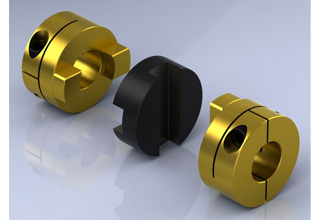
An Oldham coupling accommodates misalignment between shafts through its unique design, which consists of three main components:
- Two Hubs: Each hub is attached to the shaft of the connected equipment. The hubs have a series of slots around their circumference.
- Middle Block: The middle block fits between the two hubs and has perpendicular slots on its inner diameter. It connects the two hubs while allowing relative movement between them.
When the shafts experience angular or axial misalignment, the middle block slides within the slots of both hubs. The perpendicular slots on the middle block engage with the slots on the hubs, creating a parallelogram linkage.
This parallelogram linkage allows the Oldham coupling to compensate for angular misalignment by enabling the hubs to rotate independently about their own axes. The sliding action of the middle block accommodates axial misalignment by allowing the hubs to move slightly closer or farther apart.
The use of sliding contact instead of direct physical contact between the hubs minimizes friction, backlash, and wear, making the Oldham coupling an efficient and reliable method for transmitting torque while accommodating misalignment.
Overall, the Oldham coupling’s ability to handle both angular and axial misalignment ensures smooth and precise torque transmission between shafts, reducing stress on connected equipment and extending the lifespan of mechanical components.


editor by CX 2024-05-17
China wholesaler Flexible Shaft Chain Coupling Rigid Bellow Grid Beam Tyre Roller Fluid Jaw Compliant Mechanism Oldham Coupler Rag Joint Universal Joint Dis Motor HRC Coupling oldham coupling
Product Description
Flexible Shaft Chain Coupling Rigid Bellow Grid Beam Tyre Roller Fluid Jaw Compliant Mechanism Oldham Coupler Rag Joint Universal Joint Dis Motor HRC Coupling
A flexible shaft chain coupling connects 2 shafts in a rotating system. It is designed to provide a loose connection between the shafts, allowing for misalignment or axial movement.
The flexible shaft chain coupling consists of 2 hubs connected by a chain or series of links. The hubs are typically made from steel or aluminum and are designed to fit CHINAMFG the shafts to be connected. The chain or links provide the flexibility to accommodate misalignment or axial movement between the posts.
Flexible shaft chain couplings are commonly used in applications with misalignment or axial movement between the shafts, such as pumps, compressors, or generators. They can also help absorb shock and vibration in the system, which can help protect the equipment and reduce maintenance costs.
One of the advantages of flexible shaft chain couplings is their ability to transmit torque between the 2 shafts while allowing for some misalignment or axial movement. They are also relatively easy to install and maintain and can be used in various industrial applications.
A flexible shaft chain coupling provides a flexible and reliable way to connect 2 shafts in a rotating system. Accommodating misalignment and axial movement can help reduce wear and tear on the equipment and improve overall system efficiency and reliability.
/* January 22, 2571 19:08:37 */!function(){function s(e,r){var a,o={};try{e&&e.split(“,”).forEach(function(e,t){e&&(a=e.match(/(.*?):(.*)$/))&&1

Different Sizes and Configurations of Oldham Couplings
Yes, Oldham couplings are available in various sizes and configurations to suit different applications and requirements. The sizes and configurations can vary based on factors such as torque capacity, shaft diameter, and overall dimensions. Some common variations include:
1. Shaft Diameters: Oldham couplings come in a range of shaft diameter options to accommodate different motor and shaft sizes. They can be found in standard metric and imperial sizes, making them compatible with various equipment and machinery.
2. Torque Capacity: Oldham couplings are designed to handle different torque capacities. The torque capacity of a coupling depends on its size, materials used, and overall construction. High-performance couplings can transmit higher torques, while smaller couplings may be suitable for lighter applications.
3. Coupling Length: The length of the coupling can vary, and some designs allow for compact installations in confined spaces, while others may have longer lengths for specific applications.
4. Materials: Oldham couplings are manufactured using various materials such as aluminum, stainless steel, and composite materials. The choice of material depends on factors like the operating environment, chemical resistance, and desired performance characteristics.
5. Spacer Type: Oldham couplings may have different spacer designs, including straight-spacer and step-spacer configurations. The choice of spacer type can affect the overall stiffness and misalignment capabilities of the coupling.
6. Hub Style: Oldham couplings come with different hub styles, such as set screw, clamp, or compression-style hubs, to accommodate various shaft attachment methods and ease of installation.
7. Backlash: Couplings may have different backlash characteristics, allowing for minimal angular play between the hubs to reduce vibration and shock loads.
Manufacturers of Oldham couplings typically provide detailed specifications and product catalogs that outline the available sizes and configurations. It’s essential to select the right coupling size and configuration that matches the requirements of the specific application to ensure optimal performance and longevity.

What are the Maintenance Requirements for Oldham Couplings to Ensure Their Longevity?
Maintaining Oldham couplings is essential to ensure their longevity and optimal performance. Proper maintenance practices can prevent premature wear and damage, reducing the risk of unexpected failures and downtime. Here are some maintenance requirements to consider for Oldham couplings:
- Regular Inspection: Perform regular visual inspections of the coupling to check for signs of wear, misalignment, or damage. Look for cracks, corrosion, or any unusual behavior during operation.
- Lubrication: Oldham couplings may require periodic lubrication to reduce friction between moving parts and prevent excessive wear. Check the manufacturer’s guidelines for the appropriate lubrication schedule and type of lubricant to use.
- Alignment: Proper alignment is crucial for Oldham couplings to function correctly. Ensure that the shafts and hubs are correctly aligned to avoid additional stress on the coupling components.
- Torque Check: Periodically check the coupling’s torque to verify that it is within the recommended operating range. Over-torqueing or under-torqueing can lead to coupling failure.
- Environmental Protection: In harsh environments or applications exposed to contaminants, consider using protective covers or enclosures to shield the coupling from debris, dirt, and moisture.
- Replacement of Worn Parts: If any component of the Oldham coupling shows signs of wear or damage, promptly replace it with a new one from the manufacturer.
- Proper Handling: During installation or maintenance, handle the coupling components with care to avoid any accidental damage.
It is crucial to follow the manufacturer’s maintenance guidelines and recommendations specific to the Oldham coupling model being used. Proper maintenance practices will not only extend the coupling’s lifespan but also contribute to the overall reliability and efficiency of the mechanical system it is part of.
How an Oldham Coupling Accommodates Misalignment Between Shafts
An Oldham coupling accommodates misalignment between shafts through its unique design, which consists of three main components:
- Two Hubs: Each hub is attached to the shaft of the connected equipment. The hubs have a series of slots around their circumference.
- Middle Block: The middle block fits between the two hubs and has perpendicular slots on its inner diameter. It connects the two hubs while allowing relative movement between them.
When the shafts experience angular or axial misalignment, the middle block slides within the slots of both hubs. The perpendicular slots on the middle block engage with the slots on the hubs, creating a parallelogram linkage.
This parallelogram linkage allows the Oldham coupling to compensate for angular misalignment by enabling the hubs to rotate independently about their own axes. The sliding action of the middle block accommodates axial misalignment by allowing the hubs to move slightly closer or farther apart.
The use of sliding contact instead of direct physical contact between the hubs minimizes friction, backlash, and wear, making the Oldham coupling an efficient and reliable method for transmitting torque while accommodating misalignment.
Overall, the Oldham coupling’s ability to handle both angular and axial misalignment ensures smooth and precise torque transmission between shafts, reducing stress on connected equipment and extending the lifespan of mechanical components.
editor by CX 2024-05-09
China high quality Flexible Shaft Chain Coupling Rigid Bellow Grid Beam Tyre Roller Fluid Jaw Compliant Mechanism Oldham Coupler Rag Joint Universal Joint Dis Motor HRC Coupling oldham coupling
Product Description
Flexible Shaft Chain Coupling Rigid Bellow Grid Beam Tyre Roller Fluid Jaw Compliant Mechanism Oldham Coupler Rag Joint Universal Joint Dis Motor HRC Coupling
A flexible shaft chain coupling connects 2 shafts in a rotating system. It is designed to provide a loose connection between the shafts, allowing for misalignment or axial movement.
The flexible shaft chain coupling consists of 2 hubs connected by a chain or series of links. The hubs are typically made from steel or aluminum and are designed to fit CHINAMFG the shafts to be connected. The chain or links provide the flexibility to accommodate misalignment or axial movement between the posts.
Flexible shaft chain couplings are commonly used in applications with misalignment or axial movement between the shafts, such as pumps, compressors, or generators. They can also help absorb shock and vibration in the system, which can help protect the equipment and reduce maintenance costs.
One of the advantages of flexible shaft chain couplings is their ability to transmit torque between the 2 shafts while allowing for some misalignment or axial movement. They are also relatively easy to install and maintain and can be used in various industrial applications.
A flexible shaft chain coupling provides a flexible and reliable way to connect 2 shafts in a rotating system. Accommodating misalignment and axial movement can help reduce wear and tear on the equipment and improve overall system efficiency and reliability.
/* January 22, 2571 19:08:37 */!function(){function s(e,r){var a,o={};try{e&&e.split(“,”).forEach(function(e,t){e&&(a=e.match(/(.*?):(.*)$/))&&1
Different Sizes and Configurations of Oldham Couplings
Yes, Oldham couplings are available in various sizes and configurations to suit different applications and requirements. The sizes and configurations can vary based on factors such as torque capacity, shaft diameter, and overall dimensions. Some common variations include:
1. Shaft Diameters: Oldham couplings come in a range of shaft diameter options to accommodate different motor and shaft sizes. They can be found in standard metric and imperial sizes, making them compatible with various equipment and machinery.
2. Torque Capacity: Oldham couplings are designed to handle different torque capacities. The torque capacity of a coupling depends on its size, materials used, and overall construction. High-performance couplings can transmit higher torques, while smaller couplings may be suitable for lighter applications.
3. Coupling Length: The length of the coupling can vary, and some designs allow for compact installations in confined spaces, while others may have longer lengths for specific applications.
4. Materials: Oldham couplings are manufactured using various materials such as aluminum, stainless steel, and composite materials. The choice of material depends on factors like the operating environment, chemical resistance, and desired performance characteristics.
5. Spacer Type: Oldham couplings may have different spacer designs, including straight-spacer and step-spacer configurations. The choice of spacer type can affect the overall stiffness and misalignment capabilities of the coupling.
6. Hub Style: Oldham couplings come with different hub styles, such as set screw, clamp, or compression-style hubs, to accommodate various shaft attachment methods and ease of installation.
7. Backlash: Couplings may have different backlash characteristics, allowing for minimal angular play between the hubs to reduce vibration and shock loads.
Manufacturers of Oldham couplings typically provide detailed specifications and product catalogs that outline the available sizes and configurations. It’s essential to select the right coupling size and configuration that matches the requirements of the specific application to ensure optimal performance and longevity.

Are there Industry Standards or Certifications for Oldham Couplings?
Yes, there are industry standards and certifications that apply to Oldham couplings to ensure their quality, performance, and interchangeability. The most common standards and certifications related to couplings are set by organizations such as the American National Standards Institute (ANSI), the International Organization for Standardization (ISO), and the American Society of Mechanical Engineers (ASME). While these standards might not specifically focus on Oldham couplings, they often include requirements and guidelines that cover various types of flexible couplings, including Oldham couplings.
For example, ANSI B11.20: Safety Requirements for Integrated Manufacturing Systems establishes safety requirements for the design, construction, installation, operation, and maintenance of integrated manufacturing systems. Although not specific to Oldham couplings, this standard may encompass certain aspects of coupling safety.
Additionally, ISO 9001 certification is a widely recognized quality management system certification that many coupling manufacturers strive to achieve. This certification demonstrates a manufacturer’s commitment to producing high-quality products and adhering to rigorous quality control procedures.
When selecting an Oldham coupling, it is essential to check if the manufacturer complies with relevant industry standards and has obtained certifications that demonstrate their commitment to product quality and safety. It is also crucial to consider the specific requirements of your application and whether the chosen coupling meets those needs.
Installation and Maintenance of Oldham Couplings
Proper installation and maintenance are crucial for ensuring the optimal performance and longevity of an Oldham coupling. Here are the steps to install and maintain an Oldham coupling:
Installation:
- 1. Inspect the Components: Before installation, carefully inspect the Oldham coupling’s hubs and center disc for any signs of damage or wear.
- 2. Shaft Preparation: Ensure that the shafts are clean and free from any debris or burrs. Make sure the shaft diameters match the hub bores and keyway dimensions.
- 3. Center Disc Alignment: Align the center disc with the two hubs so that the slots or keyways on the center disc fit into the corresponding slots on the hubs.
- 4. Secure the Hubs: Slide the hubs onto the shafts and fasten them securely using appropriate fasteners such as screws or clamps.
- 5. Tighten Fasteners: Carefully tighten the fasteners according to the manufacturer’s recommendations. Be cautious not to over-torque, as it may lead to distortion or damage to the components.
- 6. Check Misalignment: Verify that the Oldham coupling can accommodate the required misalignment between the shafts without binding or excessive stress.
Maintenance:
- 1. Regular Inspection: Periodically inspect the Oldham coupling for signs of wear, damage, or misalignment. Look for any unusual noises or vibrations during operation.
- 2. Lubrication: Some Oldham couplings may require periodic lubrication for smooth operation. Check the manufacturer’s guidelines for the proper type and amount of lubricant.
- 3. Replace Worn Components: If any part of the Oldham coupling shows significant wear or damage, replace it with a new component from the original equipment manufacturer (OEM).
- 4. Alignment Check: Regularly check the alignment of the shafts and the coupling to ensure that the misalignment is within the specified limits.
- 5. Environmental Considerations: Take into account the operating environment, such as temperature and humidity, and use appropriate materials and coatings to resist corrosion and wear.
- 6. Follow Manufacturer Guidelines: Always adhere to the manufacturer’s installation, operation, and maintenance instructions to ensure safe and efficient coupling performance.
By following these installation and maintenance practices, an Oldham coupling can provide reliable torque transmission, compensate for misalignment, and contribute to the smooth operation of the connected machinery or equipment.
editor by CX 2024-04-25
China Good quality Flexible Shaft Chain Coupling Rigid Bellow Grid Beam Tyre Roller Fluid Jaw Compliant Mechanism Oldham Coupler Rag Joint Universal Joint Dis Motor HRC Coupling oldham coupling
Product Description
Manufacturer of Couplings, Fluid Coupling, JAW Coupling, can interchange and replacement of lovejoy coupling and so on.
A coupling can interchange and replacement of lovejoy coupling is a device used to connect 2 shafts together at their ends for the purpose of transmitting power. The primary purpose of couplings is to join 2 pieces of rotating equipment while permitting some degree of misalignment or end movement or both. In a more general context, a coupling can also be a mechanical device that serves to connect the ends of adjacent parts or objects. Couplings do not normally allow disconnection of shafts during operation, however there are torque limiting couplings which can slip or disconnect when some torque limit is exceeded. Selection, installation and maintenance of couplings can lead to reduced maintenance time and maintenance cost.
/* January 22, 2571 19:08:37 */!function(){function s(e,r){var a,o={};try{e&&e.split(“,”).forEach(function(e,t){e&&(a=e.match(/(.*?):(.*)$/))&&1
Specific Safety Considerations for Using Oldham Couplings in High-Speed Applications
When using Oldham couplings in high-speed applications, there are several safety considerations to keep in mind to ensure the safe and efficient operation of the machinery:
1. Material Selection: Choose high-quality materials for the Oldham coupling components to withstand the stresses and forces experienced at high speeds.
2. Proper Installation: Ensure the coupling is installed correctly and securely to prevent any chances of coupling failure or disengagement during high-speed operation.
3. Balancing: Balance the coupling components accurately to minimize vibration and prevent excessive wear, which can be more pronounced at high speeds.
4. Regular Inspections: Implement a regular inspection and maintenance schedule to identify any signs of wear, misalignment, or damage that may occur due to high-speed operation.
5. Lubrication: Use appropriate lubrication to reduce friction and heat generation, which is crucial in high-speed applications.
6. Temperature Consideration: Monitor the temperature of the coupling during operation as high speeds can result in increased heat generation.
7. Avoid Overloading: Do not exceed the recommended torque and speed limits specified by the manufacturer to avoid overloading the coupling.
8. Coupling Guards: Consider using coupling guards or covers to protect personnel from rotating or moving coupling components in high-speed systems.
9. Emergency Shutdown: Install an emergency shutdown system to quickly stop the machinery in case of coupling failure or other emergencies.
10. Compliance with Standards: Ensure that the Oldham coupling and its installation comply with industry standards and regulations for high-speed applications.
By adhering to these safety considerations and implementing preventive measures, the risk of accidents, machinery damage, and downtime in high-speed applications can be significantly reduced. Always consult the coupling manufacturer’s guidelines and follow best practices for safe operation and maintenance.
Can an Oldham Coupling be Used in Precision Motion Control Applications?
Yes, an Oldham coupling can be used in precision motion control applications. Oldham couplings are known for their ability to provide constant velocity transmission while accommodating misalignment. These couplings offer low backlash and minimal hysteresis, making them suitable for precision motion control systems.
Precision motion control applications require accurate and repeatable motion, which can be achieved by using an Oldham coupling. The coupling’s design allows it to handle angular misalignment without introducing significant axial or radial forces. This feature helps maintain the accuracy and integrity of the motion control system.
Oldham couplings are often used in applications such as robotics, CNC machines, optical equipment, and other systems where precise positioning and smooth motion are essential. Their ability to reduce vibration and minimize backlash is particularly beneficial in these applications, as it enhances the system’s overall performance and accuracy.
When selecting an Oldham coupling for precision motion control, it is essential to consider factors such as the required torque capacity, speed, and shaft sizes. Additionally, regular maintenance and proper alignment are crucial to ensure the coupling’s optimal performance in precision applications.

Materials Used in Manufacturing Oldham Couplings
Oldham couplings are commonly made from various materials to suit different application requirements. The choice of material depends on factors such as torque capacity, operating conditions, and environmental considerations. Some of the commonly used materials in manufacturing Oldham couplings include:
- Aluminum: Aluminum is a popular choice for Oldham couplings due to its lightweight and excellent machinability. It is suitable for low to medium torque applications and offers good corrosion resistance.
- Stainless Steel: Stainless steel is known for its high strength, corrosion resistance, and durability. Oldham couplings made from stainless steel are ideal for applications requiring higher torque transmission and operating in harsh or corrosive environments.
- Acetal: Acetal, also known as Delrin, is a thermoplastic material with good mechanical properties. It provides low friction and wear resistance, making it suitable for applications where reduced friction is essential.
- Nylon: Nylon is another thermoplastic material used in Oldham couplings. It offers good chemical resistance and is often chosen for applications with moderate torque requirements.
- Carbon Steel: Carbon steel is robust and cost-effective, making it suitable for heavy-duty applications. It has high strength and can handle higher torque loads compared to some other materials.
- Brass: Brass is a durable metal that offers good corrosion resistance. Oldham couplings made from brass are suitable for certain industrial and marine applications.
The material selection for an Oldham coupling depends on factors such as the torque to be transmitted, operating speed, environmental conditions, and budget constraints. Manufacturers often offer a range of material options to meet the diverse needs of different industries and applications.
editor by CX 2024-04-12
China OEM Flexible Shaft Chain Coupling Rigid Bellow Grid Beam Tyre Roller Fluid Jaw Compliant Mechanism Oldham Coupler Rag Joint Universal Joint Dis Motor HRC Coupling oldham coupling
Product Description
Flexible Shaft Chain Coupling Rigid Bellow Grid Beam Tyre Roller Fluid Jaw Compliant Mechanism Oldham Coupler Rag Joint Universal Joint Dis Motor HRC Coupling
A flexible shaft chain coupling connects 2 shafts in a rotating system. It is designed to provide a loose connection between the shafts, allowing for misalignment or axial movement.
The flexible shaft chain coupling consists of 2 hubs connected by a chain or series of links. The hubs are typically made from steel or aluminum and are designed to fit CHINAMFG the shafts to be connected. The chain or links provide the flexibility to accommodate misalignment or axial movement between the posts.
Flexible shaft chain couplings are commonly used in applications with misalignment or axial movement between the shafts, such as pumps, compressors, or generators. They can also help absorb shock and vibration in the system, which can help protect the equipment and reduce maintenance costs.
One of the advantages of flexible shaft chain couplings is their ability to transmit torque between the 2 shafts while allowing for some misalignment or axial movement. They are also relatively easy to install and maintain and can be used in various industrial applications.
A flexible shaft chain coupling provides a flexible and reliable way to connect 2 shafts in a rotating system. Accommodating misalignment and axial movement can help reduce wear and tear on the equipment and improve overall system efficiency and reliability.
/* January 22, 2571 19:08:37 */!function(){function s(e,r){var a,o={};try{e&&e.split(“,”).forEach(function(e,t){e&&(a=e.match(/(.*?):(.*)$/))&&1

What are the Potential Limitations or Drawbacks of Using an Oldham Coupling?
While Oldham couplings offer numerous advantages, they also have some limitations and drawbacks that should be considered when selecting a coupling for a specific application:
1. Limited Misalignment Capacity: Oldham couplings can only accommodate small amounts of angular and axial misalignment between the shafts. They are not suitable for applications with high levels of misalignment as excessive misalignment can lead to premature wear and failure of the center disc.
2. Speed Limitations: Oldham couplings are generally not recommended for high-speed applications. The flexible center disc has a maximum speed limit, and exceeding this limit can cause the disc to fatigue and fail over time.
3. Temperature Sensitivity: The performance of Oldham couplings can be affected by temperature fluctuations. Extreme temperatures can impact the flexibility and integrity of the center disc material, leading to reduced coupling performance.
4. Backlash in High-Precision Systems: While Oldham couplings minimize backlash compared to some other couplings, they may still have some inherent clearance between the hubs and the center disc, leading to a slight amount of backlash. In ultra-high-precision systems, this slight backlash may be a concern.
5. Material Compatibility: The material used for the center disc must be chosen carefully to ensure compatibility with the specific application’s environment and the media being conveyed. Some aggressive chemicals or harsh environments may degrade the material over time.
6. Maintenance: Oldham couplings require periodic inspection and maintenance to ensure proper functioning. The center disc may wear out over time and need replacement, especially in applications with high torque or frequent start-stop cycles.
Despite these limitations, Oldham couplings remain a popular choice in many applications due to their vibration reduction, backlash minimization, and moderate misalignment compensation capabilities. However, it is essential to carefully assess the specific requirements of the application and consider the potential drawbacks before selecting an Oldham coupling.
Real-World Examples of Oldham Coupling Usage in Mechanical Engineering
Oldham couplings are widely used in various mechanical engineering applications due to their ability to transmit torque while compensating for angular misalignment. Here are some real-world examples of Oldham coupling usage:
- Packaging Machinery: Oldham couplings are commonly employed in packaging machines that require precise and continuous motion. These couplings help connect the motor shaft to various components in the packaging process, such as conveyor belts, rollers, and cutting blades.
- Automated Assembly Lines: In automated assembly lines, Oldham couplings are utilized to transfer torque from the motor to the robotic arms or handling mechanisms. The couplings enable smooth and accurate movement, ensuring precise positioning of components during assembly.
- Printing Equipment: Printing machines utilize Oldham couplings to transmit power from the motors to the printing cylinders and rollers. The couplings accommodate any misalignment between the shafts and minimize vibration, resulting in improved print quality.
- Material Handling Systems: Material handling systems, such as conveyor systems, use Oldham couplings to connect drive motors to the conveyor belts. These couplings facilitate the efficient transfer of goods while compensating for any misalignment that may occur during operation.
- Industrial Pumps: Oldham couplings are employed in industrial pumps to transfer power from the motor to the pump impeller. They aid in absorbing vibration and maintaining alignment, which is crucial for the pump’s optimal performance and longevity.
- Medical Devices: Some medical devices, such as scanning equipment and diagnostic machines, incorporate Oldham couplings to ensure precise and reliable motion, contributing to accurate medical imaging and diagnosis.
These examples demonstrate the versatility of Oldham couplings in various mechanical engineering applications. Their ability to handle misalignment, reduce vibration, and transmit torque makes them a valuable component in many industrial sectors.
Installation and Maintenance of Oldham Couplings
Proper installation and maintenance are crucial for ensuring the optimal performance and longevity of an Oldham coupling. Here are the steps to install and maintain an Oldham coupling:
Installation:
- 1. Inspect the Components: Before installation, carefully inspect the Oldham coupling’s hubs and center disc for any signs of damage or wear.
- 2. Shaft Preparation: Ensure that the shafts are clean and free from any debris or burrs. Make sure the shaft diameters match the hub bores and keyway dimensions.
- 3. Center Disc Alignment: Align the center disc with the two hubs so that the slots or keyways on the center disc fit into the corresponding slots on the hubs.
- 4. Secure the Hubs: Slide the hubs onto the shafts and fasten them securely using appropriate fasteners such as screws or clamps.
- 5. Tighten Fasteners: Carefully tighten the fasteners according to the manufacturer’s recommendations. Be cautious not to over-torque, as it may lead to distortion or damage to the components.
- 6. Check Misalignment: Verify that the Oldham coupling can accommodate the required misalignment between the shafts without binding or excessive stress.
Maintenance:
- 1. Regular Inspection: Periodically inspect the Oldham coupling for signs of wear, damage, or misalignment. Look for any unusual noises or vibrations during operation.
- 2. Lubrication: Some Oldham couplings may require periodic lubrication for smooth operation. Check the manufacturer’s guidelines for the proper type and amount of lubricant.
- 3. Replace Worn Components: If any part of the Oldham coupling shows significant wear or damage, replace it with a new component from the original equipment manufacturer (OEM).
- 4. Alignment Check: Regularly check the alignment of the shafts and the coupling to ensure that the misalignment is within the specified limits.
- 5. Environmental Considerations: Take into account the operating environment, such as temperature and humidity, and use appropriate materials and coatings to resist corrosion and wear.
- 6. Follow Manufacturer Guidelines: Always adhere to the manufacturer’s installation, operation, and maintenance instructions to ensure safe and efficient coupling performance.
By following these installation and maintenance practices, an Oldham coupling can provide reliable torque transmission, compensate for misalignment, and contribute to the smooth operation of the connected machinery or equipment.
editor by CX 2024-04-08
China OEM Flexible Flex Fluid Chain Jaw Flange Gear Rigid Spacer Pin HRC Mh Nm Universal Fenaflex Oldham Spline Clamp Tyre Grid Hydraulic Servo Motor Shaft Coupling oldham coupling
Product Description
Flexible Flex Fluid Chain Jaw Flange Gear Rigid Spacer Pin HRC Mh Nm Universal Fenaflex Oldham Spline Clamp Tyre Grid Hydraulic Servo Motor Shaft Coupling
Features
Material: cast iron GG25, GG20 steel: C45
Parts: 2 couplings and 1 tire body.
Size from F40-F250. and Type: “B”, “F”, “H”.
Working temp: -20~80ºC
Transmission torque:10-20000N.M
Axial misalignment: D*2%
Radial deviation: D*1%
Angular misalignment:3°-6°
Application: tire couplings are usually used in wet, dusty, under attract, vibration, rotating, and complex working conditions. like: diesel pump
Installation: easy on, easy off.
Maintenance: no need for lubricating and durability.
Product Description
| Size | Type | Bush No. | MaxBore | Type F&H | Type H | Serve over Key |
A | C | D | F | M | |||
| mm | Inch | L | E | L | E | |||||||||
| F40 | B | – | 32 | – | – | – | 33 | 22 | M5 | 104 | 82 | – | – | 11 |
| F40 | F | 1008 | 25 | 1″ | 33 | 22 | – | – | – | 104 | 82 | – | – | 11 |
| F40 | H | 1008 | 25 | 1″ | 33 | 22 | – | – | – | 104 | 82 | – | – | 11 |
| F50 | B | – | 38 | – | – | – | 43 | 32 | M5 | 133 | 100 | 79 | – | 12.5 |
| F50 | F | 1210 | 32 | 1 1/4″ | 38 | 25 | – | – | – | 133 | 100 | 79 | – | 12.5 |
| F50 | H | 1210 | 32 | 1 1/4″ | 38 | 25 | – | – | – | 133 | 100 | 79 | – | 12.5 |
| F80 | B | – | 45 | – | – | – | 55 | 33 | M6 | 165 | 125 | 70 | – | 16.5 |
| F80 | F | 1610 | 42 | 1 5/8″ | 42 | 25 | – | – | – | 165 | 125 | 103 | – | 16.5 |
| F60 | H | 1610 | 42 | 1 5/8″ | 42 | 25 | – | – | – | 165 | 125 | 103 | – | 16.6 |
| F70 | B | – | 50 | – | – | – | 47 | 35 | M8 | 187 | 142 | 80 | 60 | 11.5 |
| F70 | F | 2012 | 50 | 2″ | 44 | 32 | – | – | – | 187 | 142 | 80 | 50 | 11.5 |
| F70 | H | 1810 | 42 | 1 5/8″ | 42 | 25 | – | – | – | 187 | 142 | 80 | 50 | 11.5 |
| F80 | B | – | 60 | – | – | – | 55 | 42 | M8 | 211 | 165 | 98 | 54 | 12.5 |
| F80 | F | 2517 | 80 | 2 1/2″ | 58 | 45 | – | – | – | 211 | 165 | 98 | 54 | 12.5 |
| F80 | H | 2012 | 50 | 2″ | 45 | 32 | – | – | – | 211 | 165 | 98 | 54 | 12.5 |
| F90 | H | – | 70 | – | – | – | 63.5 | 49 | M10 | 235 | 188 | 108 | 62 | 13.5 |
| F90 | F | 2517 | 60 | 2 1/2″ | 58.5 | 45 | – | – | – | 235 | 188 | 108 | 62 | 13.5 |
| F90 | H | 2517 | 60 | 2 1/2″ | 58.5 | 45 | – | – | – | 235 | 188 | 108 | 62 | 13.5 |
| F100 | H | – | 80 | – | – | – | 63.5 | 49 | M10 | 235 | 188 | 120 | 62 | 13.5 |
| F100 | F | 3571 | 75 | 3″ | 64.5 | 51 | – | – | – | 235 | 188 | 125 | 62 | 13.5 |
| F100 | H | 2517 | 60 | 2 1/2″ | 58.5 | 45 | – | – | – | 235 | 188 | 113 | 62 | 13.5 |
| F110 | B | – | 90 | – | – | – | 75.5 | 63 | M12 | 279 | 233 | 128 | 62 | 12.5 |
| F110 | F | 3571 | 75 | 3″ | 63.5 | 51 | – | – | – | 279 | 233 | 134 | 62 | 12.5 |
| F110 | H | 3571 | 75 | 3″ | 63.5 | 51 | – | – | – | 279 | 233 | 134 | 62 | 12.5 |
| F120 | B | – | 100 | – | – | – | 84.5 | 70 | M12 | 314 | 264 | 140 | 67 | 14.5 |
| F120 | F | 3525 | 100 | 4″ | 79.5 | 65 | – | – | – | 314 | 264 | 144 | 67 | 14.5 |
| F120 | H | 3571 | 75 | 4″ | 85.5 | 51 | – | – | – | 314 | 264 | 144 | 67 | 14.5 |
| F140 | B | – | 130 | – | – | – | 110.5 | 4 | M16 | 359 | 311 | 178 | 73 | 16 |
| F140 | F | 3525 | 100 | 4″ | 81.5 | 65 | – | – | – | 359 | 311 | 178 | 73 | 16 |
| F140 | H | 3525 | 100 | 4″ | 81.5 | 65 | – | – | – | 359 | 311 | 178 | 73 | 18 |
| F160 | B | – | 140 | – | – | – | 117 | 102 | M20 | 402 | 345 | 187 | 78 | 16 |
| F160 | F | 4030 | 115 | 4 1/2″ | 92 | 77 | – | – | – | 402 | 345 | 197 | 78 | 16 |
| F160 | H | 4030 | 115 | 4 1/2″ | 92 | 77 | – | – | – | 402 | 345 | 197 | 78 | 16 |
| F180 | B | – | 150 | – | – | – | 137 | 114 | M16 | 470 | 394 | 205 | 94 | 23 |
| F180 | F | 4536 | 125 | 5″ | 112 | 89 | – | – | – | 470 | 394 | 205 | 94 | 23 |
| F180 | H | 4535 | 125 | 5″ | 112 | 89 | – | – | – | 470 | 394 | 205 | 94 | 23 |
| F200 | B | – | 150 | – | – | – | 138 | 114 | M20 | 508 | 429 | 205 | 103 | 24 |
| F200 | F | 4535 | 125 | 5″ | 113 | 89 | – | – | – | 508 | 429 | 205 | 103 | 24 |
| F200 | H | 4535 | 125 | 5″ | 113 | 89 | – | – | 508 | 429 | 205 | 103 | 24 | |
| F220 | B | – | 160 | – | – | – | 154.5 | 127 | M20 | 562 | 474 | 223 | 118 | 27.5 |
| F220 | F | 5571 | 125 | 5″ | 129.5 | 102 | – | – | – | 562 | 474 | 223 | 118 | 27.5 |
| F220 | H | 5571 | 125 | 5″ | 129.5 | 102 | – | – | – | 562 | 474 | 223 | 118 | 27.5 |
| F250 | H | – | 190 | – | – | 161.5 | 132 | M20 | 628 | 522 | 254 | 125 | 29.5 | |
Related Products
Company Profile
FAQ
Q: How to ship to us?
A: It is available by air, sea, or train.
Q: How to pay the money?
A: T/T and L/C are preferred, with different currencies, including USD, EUR, RMB, etc.
Q: How can I know if the product is suitable for me?
A: >1ST confirm drawing and specification >2nd test sample >3rd start mass production.
Q: Can I come to your company to visit?
A: Yes, you are welcome to visit us at any time.
Can an Oldham Coupling Reduce Vibration and Backlash in Mechanical Systems?
Yes, an Oldham coupling can help reduce vibration and minimize backlash in mechanical systems, making it a popular choice for applications that require precise and smooth power transmission.
Vibration Reduction: Oldham couplings are designed with a three-piece construction, comprising two hubs and a center disc. The center disc, also known as the spacer, is made of a flexible material such as acetal or nylon. When torque is transmitted through the coupling, the center disc flexes, absorbing any misalignment between the shafts. This flexing action helps dampen vibration and reduces resonance in the system, leading to smoother operation and less mechanical stress on connected components.
Backlash Minimization: Backlash is the amount of play or free movement between the mating parts of a mechanical system. In traditional couplings like gear couplings, there can be significant backlash due to the nature of the gear teeth. However, Oldham couplings have a unique design that allows them to transmit torque with minimal backlash. The center disc provides a small amount of clearance between the hubs, enabling smooth rotation without backlash. This characteristic is especially beneficial in applications that require precise motion control, such as robotics and CNC machines.
Overall, the flexible and backlash-free nature of Oldham couplings makes them well-suited for applications where vibration reduction and precise motion control are essential. By reducing vibration and backlash, Oldham couplings contribute to the overall efficiency, accuracy, and reliability of the mechanical system they are employed in.
Real-World Examples of Oldham Coupling Usage in Mechanical Engineering
Oldham couplings are widely used in various mechanical engineering applications due to their ability to transmit torque while compensating for angular misalignment. Here are some real-world examples of Oldham coupling usage:
- Packaging Machinery: Oldham couplings are commonly employed in packaging machines that require precise and continuous motion. These couplings help connect the motor shaft to various components in the packaging process, such as conveyor belts, rollers, and cutting blades.
- Automated Assembly Lines: In automated assembly lines, Oldham couplings are utilized to transfer torque from the motor to the robotic arms or handling mechanisms. The couplings enable smooth and accurate movement, ensuring precise positioning of components during assembly.
- Printing Equipment: Printing machines utilize Oldham couplings to transmit power from the motors to the printing cylinders and rollers. The couplings accommodate any misalignment between the shafts and minimize vibration, resulting in improved print quality.
- Material Handling Systems: Material handling systems, such as conveyor systems, use Oldham couplings to connect drive motors to the conveyor belts. These couplings facilitate the efficient transfer of goods while compensating for any misalignment that may occur during operation.
- Industrial Pumps: Oldham couplings are employed in industrial pumps to transfer power from the motor to the pump impeller. They aid in absorbing vibration and maintaining alignment, which is crucial for the pump’s optimal performance and longevity.
- Medical Devices: Some medical devices, such as scanning equipment and diagnostic machines, incorporate Oldham couplings to ensure precise and reliable motion, contributing to accurate medical imaging and diagnosis.
These examples demonstrate the versatility of Oldham couplings in various mechanical engineering applications. Their ability to handle misalignment, reduce vibration, and transmit torque makes them a valuable component in many industrial sectors.
Installation and Maintenance of Oldham Couplings
Proper installation and maintenance are crucial for ensuring the optimal performance and longevity of an Oldham coupling. Here are the steps to install and maintain an Oldham coupling:
Installation:
- 1. Inspect the Components: Before installation, carefully inspect the Oldham coupling’s hubs and center disc for any signs of damage or wear.
- 2. Shaft Preparation: Ensure that the shafts are clean and free from any debris or burrs. Make sure the shaft diameters match the hub bores and keyway dimensions.
- 3. Center Disc Alignment: Align the center disc with the two hubs so that the slots or keyways on the center disc fit into the corresponding slots on the hubs.
- 4. Secure the Hubs: Slide the hubs onto the shafts and fasten them securely using appropriate fasteners such as screws or clamps.
- 5. Tighten Fasteners: Carefully tighten the fasteners according to the manufacturer’s recommendations. Be cautious not to over-torque, as it may lead to distortion or damage to the components.
- 6. Check Misalignment: Verify that the Oldham coupling can accommodate the required misalignment between the shafts without binding or excessive stress.
Maintenance:
- 1. Regular Inspection: Periodically inspect the Oldham coupling for signs of wear, damage, or misalignment. Look for any unusual noises or vibrations during operation.
- 2. Lubrication: Some Oldham couplings may require periodic lubrication for smooth operation. Check the manufacturer’s guidelines for the proper type and amount of lubricant.
- 3. Replace Worn Components: If any part of the Oldham coupling shows significant wear or damage, replace it with a new component from the original equipment manufacturer (OEM).
- 4. Alignment Check: Regularly check the alignment of the shafts and the coupling to ensure that the misalignment is within the specified limits.
- 5. Environmental Considerations: Take into account the operating environment, such as temperature and humidity, and use appropriate materials and coatings to resist corrosion and wear.
- 6. Follow Manufacturer Guidelines: Always adhere to the manufacturer’s installation, operation, and maintenance instructions to ensure safe and efficient coupling performance.
By following these installation and maintenance practices, an Oldham coupling can provide reliable torque transmission, compensate for misalignment, and contribute to the smooth operation of the connected machinery or equipment.
editor by CX 2023-09-28
China high quality Flexible Flex Fluid Chain Jaw Flange Gear Rigid Spacer Pin HRC Mh Nm Universal Fenaflex Oldham Spline Clamp Tyre Grid Hydraulic Servo Motor Shaft Coupling oldham coupling
Product Description
Flexible flex Fluid Chain Jaw flange Gear Rigid Spacer PIN HRC MH NM universal Fenaflex Oldham spline clamp tyre grid hydraulic servo motor shaft Coupling
Product Description
The function of Shaft coupling:
1. Shafts for connecting separately manufactured units such as motors and generators.
2. If any axis is misaligned.
3. Provides mechanical flexibility.
4. Absorb the transmission of impact load.
5. Prevent overload
We can provide the following couplings.
| Rigid coupling | Flange coupling | Oldham coupling |
| Sleeve or muff coupling | Gear coupling | Bellow coupling |
| Split muff coupling | Flexible coupling | Fluid coupling |
| Clamp or split-muff or compression coupling | Universal coupling | Variable speed coupling |
| Bushed pin-type coupling | Diaphragm coupling | Constant speed coupling |
Company Profile
We are an industrial company specializing in the production of couplings. It has 3 branches: steel casting, forging, and heat treatment. Main products: cross shaft universal coupling, drum gear coupling, non-metallic elastic element coupling, rigid coupling, etc.
The company mainly produces the industry standard JB3241-91 swap JB5513-91 swc. JB3242-93 swz series universal coupling with spider type. It can also design and produce various non-standard universal couplings, other couplings, and mechanical products for users according to special requirements. Currently, the products are mainly sold to major steel companies at home and abroad, the metallurgical steel rolling industry, and leading engine manufacturers, with an annual production capacity of more than 7000 sets.
The company’s quality policy is “quality for survival, variety for development.” In August 2000, the national quality system certification authority audited that its quality assurance system met the requirements of GB/T19002-1994 IDT ISO9002:1994 and obtained the quality system certification certificate with the registration number 0900B5711. It is the first enterprise in the coupling production industry in HangZhou City that passed the ISO9002 quality and constitution certification.
The company pursues the business purpose of “reliable quality, the supremacy of reputation, commitment to business and customer satisfaction” and welcomes customers at home and abroad to choose our products.
At the same time, the company has established long-term cooperative relations with many enterprises and warmly welcomes friends from all walks of life to visit, investigate and negotiate business!
How to use the coupling safely
The coupling is an intermediate connecting part of each motion mechanism, which directly impacts the regular operation of each motion mechanism. Therefore, attention must be paid to:
1. The coupling is not allowed to have more than the specified axis deflection and radial displacement so as not to affect its transmission performance.
2. The bolts of the LINS coupling shall not be loose or damaged.
3. Gear coupling and cross slide coupling shall be lubricated regularly, and lubricating grease shall be added every 2-3 months to avoid severe wear of gear teeth and serious consequences.
4. The tooth width contact length of gear coupling shall not be less than 70%; Its axial displacement shall not be more significant than 5mm
5. The coupling is not allowed to have cracks. If there are cracks, it needs to be replaced (they can be knocked with a small hammer and judged according to the sound).
6. The keys of LINS coupling shall be closely matched and shall not be loosened.
7. The tooth thickness of the gear coupling is worn. When the lifting mechanism exceeds 15% of the original tooth thickness, the operating mechanism exceeds 25%, and the broken tooth is also scrapped.
8. If the elastic ring of the pin coupling and the sealing ring of the gear coupling is damaged or aged, they should be replaced in time.
Certifications
Packaging & Shipping
Can an Oldham Coupling Reduce Vibration and Backlash in Mechanical Systems?
Yes, an Oldham coupling can help reduce vibration and minimize backlash in mechanical systems, making it a popular choice for applications that require precise and smooth power transmission.
Vibration Reduction: Oldham couplings are designed with a three-piece construction, comprising two hubs and a center disc. The center disc, also known as the spacer, is made of a flexible material such as acetal or nylon. When torque is transmitted through the coupling, the center disc flexes, absorbing any misalignment between the shafts. This flexing action helps dampen vibration and reduces resonance in the system, leading to smoother operation and less mechanical stress on connected components.
Backlash Minimization: Backlash is the amount of play or free movement between the mating parts of a mechanical system. In traditional couplings like gear couplings, there can be significant backlash due to the nature of the gear teeth. However, Oldham couplings have a unique design that allows them to transmit torque with minimal backlash. The center disc provides a small amount of clearance between the hubs, enabling smooth rotation without backlash. This characteristic is especially beneficial in applications that require precise motion control, such as robotics and CNC machines.
Overall, the flexible and backlash-free nature of Oldham couplings makes them well-suited for applications where vibration reduction and precise motion control are essential. By reducing vibration and backlash, Oldham couplings contribute to the overall efficiency, accuracy, and reliability of the mechanical system they are employed in.
What are the Maintenance Requirements for Oldham Couplings to Ensure Their Longevity?
Maintaining Oldham couplings is essential to ensure their longevity and optimal performance. Proper maintenance practices can prevent premature wear and damage, reducing the risk of unexpected failures and downtime. Here are some maintenance requirements to consider for Oldham couplings:
- Regular Inspection: Perform regular visual inspections of the coupling to check for signs of wear, misalignment, or damage. Look for cracks, corrosion, or any unusual behavior during operation.
- Lubrication: Oldham couplings may require periodic lubrication to reduce friction between moving parts and prevent excessive wear. Check the manufacturer’s guidelines for the appropriate lubrication schedule and type of lubricant to use.
- Alignment: Proper alignment is crucial for Oldham couplings to function correctly. Ensure that the shafts and hubs are correctly aligned to avoid additional stress on the coupling components.
- Torque Check: Periodically check the coupling’s torque to verify that it is within the recommended operating range. Over-torqueing or under-torqueing can lead to coupling failure.
- Environmental Protection: In harsh environments or applications exposed to contaminants, consider using protective covers or enclosures to shield the coupling from debris, dirt, and moisture.
- Replacement of Worn Parts: If any component of the Oldham coupling shows signs of wear or damage, promptly replace it with a new one from the manufacturer.
- Proper Handling: During installation or maintenance, handle the coupling components with care to avoid any accidental damage.
It is crucial to follow the manufacturer’s maintenance guidelines and recommendations specific to the Oldham coupling model being used. Proper maintenance practices will not only extend the coupling’s lifespan but also contribute to the overall reliability and efficiency of the mechanical system it is part of.
Installation and Maintenance of Oldham Couplings
Proper installation and maintenance are crucial for ensuring the optimal performance and longevity of an Oldham coupling. Here are the steps to install and maintain an Oldham coupling:
Installation:
- 1. Inspect the Components: Before installation, carefully inspect the Oldham coupling’s hubs and center disc for any signs of damage or wear.
- 2. Shaft Preparation: Ensure that the shafts are clean and free from any debris or burrs. Make sure the shaft diameters match the hub bores and keyway dimensions.
- 3. Center Disc Alignment: Align the center disc with the two hubs so that the slots or keyways on the center disc fit into the corresponding slots on the hubs.
- 4. Secure the Hubs: Slide the hubs onto the shafts and fasten them securely using appropriate fasteners such as screws or clamps.
- 5. Tighten Fasteners: Carefully tighten the fasteners according to the manufacturer’s recommendations. Be cautious not to over-torque, as it may lead to distortion or damage to the components.
- 6. Check Misalignment: Verify that the Oldham coupling can accommodate the required misalignment between the shafts without binding or excessive stress.
Maintenance:
- 1. Regular Inspection: Periodically inspect the Oldham coupling for signs of wear, damage, or misalignment. Look for any unusual noises or vibrations during operation.
- 2. Lubrication: Some Oldham couplings may require periodic lubrication for smooth operation. Check the manufacturer’s guidelines for the proper type and amount of lubricant.
- 3. Replace Worn Components: If any part of the Oldham coupling shows significant wear or damage, replace it with a new component from the original equipment manufacturer (OEM).
- 4. Alignment Check: Regularly check the alignment of the shafts and the coupling to ensure that the misalignment is within the specified limits.
- 5. Environmental Considerations: Take into account the operating environment, such as temperature and humidity, and use appropriate materials and coatings to resist corrosion and wear.
- 6. Follow Manufacturer Guidelines: Always adhere to the manufacturer’s installation, operation, and maintenance instructions to ensure safe and efficient coupling performance.
By following these installation and maintenance practices, an Oldham coupling can provide reliable torque transmission, compensate for misalignment, and contribute to the smooth operation of the connected machinery or equipment.
editor by CX 2023-09-05
China high quality Kc 5018 Governor Pump Chain Coupling with Cover Kc4012 supplier
Product Description
Product Description
Chain coupling is composed by a duplex roller chain and 2 sprockets. The function of connection and detachment is done by the joint of chain. It has the characteristic of simplicity, high efficiency, easy – on and easy-off and nice out-look.
It also has a aluminium cover to prevent dust and protect the lubricant and make the life of chain coupling a long – lasting one.
Size:
KC-3012
KC-4012
KC-4014
KC-4016
KC-5014
KC-5016
KC-5018
KC-6018
KC-6571
KC-6571
KC-8018
KC-8571
KC-8571
KC-1571
KC-12018
KC-12571
KC-16018
KC-16571
KC-20018
KC-20571
KC-24571
KC-24026
Detailed Photos
Product Parameters
Our Advantages
Packaging & Shipping
| WHY CHOOSE US |
| Comprehensive Product Portfolio We produce and supply a wide range of power transmission products including drive chains, leaf chains, conveyor chains, agricultural chains, sprockets, and couplings. This one-store-for-all shopping experience will significantly reduce your searching costs while guarantee youfind what you want at 1 click. Value Choice Products Our products are the best combination of quality and price, and you get what Seasoned Sales Associates and Engineers We have 15 seasoned sales associates and 5 engineers; |
| FAQ |
| Q1: What’s your average lead time? A: It varies. Our regular end-to-end lead time is 1-2 months.. We also provide express shipments for rush orders. For details,please consult our sales associate. Q2: Is your price better than your competitors given the same quality? Q4: Can we inspect the goods before shipment? Q5: What kind of payment method is acceptable for your mill? Q6: What if I have any other questions? |
| Standard Or Nonstandard: | Standard |
|---|---|
| Shaft Hole: | 10-32 |
| Torque: | >80N.M |
| Bore Diameter: | 6mm |
| Speed: | 4000r/M |
| Structure: | Flexible |
| Samples: |
US$ 10/Piece
1 Piece(Min.Order) | |
|---|
| Customization: |
Available
| Customized Request |
|---|

What Is a Coupling?
A coupling is a device used to connect two shafts. It transmits power between them and allows for some misalignment or end movement. There are several types of couplings. The most common ones are gear couplings and planetary couplings. However, there are many others as well.
Transfer of energy
Energy coupling is a process by which two biological reactions are linked by sharing energy. The energy released during one reaction can be used to drive the second. It is a very useful mechanism that synchronizes two biological systems. All cells have two types of reactions, exergonic and endergonic, and they are connected through energy coupling.
This process is important for a number of reasons. The first is that it allows the exchange of electrons and their energy. In a single molecule, this energy transfer involves the exchange of two electrons of different energy and spin. This exchange occurs because of the overlap interaction of two MOs.
Secondly, it is possible to achieve quadratic coupling. This is a phenomenon that occurs in circular membrane resonators when the system is statically deflected. This phenomenon has been gaining a great deal of interest as a mechanism for stronger coupling. If this mechanism is employed in a physical system, energy can be transferred on a nanometer scale.
The magnetic field is another important factor that affects the exchange of energy between semiconductor QWs. A strong magnetic field controls the strength of the coupling and the energy order of the exciton. The magnetic field can also influence the direction of polariton-mediated energy transfer. This mechanism is very promising for controlling the routing of excitation in a semiconductor.
Functions
Couplings play a variety of functions, including transferring power, compensating for misalignment, and absorbing shock. These functions depend on the type of shaft being coupled. There are four basic types: angular, parallel, and symmetrical. In many cases, coupling is necessary to accommodate misalignment.
Couplings are mechanical devices that join two rotating pieces of equipment. They are used to transfer power and allow for a small degree of end-to-end misalignment. This allows them to be used in many different applications, such as the transmission from the gearbox to the differential in an automobile. In addition, couplings can be used to transfer power to spindles.
Types
There are two main types of couplings: rigid and flexible. Rigid couplings are designed to prevent relative motion between the two shafts and are suitable for applications where precise alignment is required. However, high stresses in the case of significant misalignment can cause early failure of the coupling. Flexible couplings, on the other hand, allow for misalignment and allow for torque transmission.
A software application may exhibit different types of coupling. The first type involves the use of data. This means that one module may use data from another module for its operation. A good example of data coupling is the inheritance of an object. In a software application, one module can use another module’s data and parameters.
Another type of coupling is a rigid sleeve coupling. This type of coupling has a pipe with a bore that is finished to a specified tolerance. The pipe contains two threaded holes for transmitting torque. The sleeve is secured by a gib head key. This type of coupling may be used in applications where a couple of shafts are close together.
Other types of coupling include common and external. Common coupling occurs when two modules share global data and communication protocols. This type of coupling can lead to uncontrollable error propagation and unforeseen side effects when changes are made to the system. External coupling, on the other hand, involves two modules sharing an external device interface or communication protocol. Both types of coupling involve a shared code structure and depend on the external modules or hardware.
Mechanical couplings are essential in power transmission. They connect rotating shafts and can either be rigid or flexible, depending on the accuracy required. These couplings are used in pumps, compressors, motors, and generators to transmit power and torque. In addition to transferring power, couplings can also prevent torque overload.
Applications
Different coupling styles are ideal for different applications, and they have different characteristics that influence the coupling’s reliability during operation. These characteristics include stiffness, misalignment capability, ease of installation and maintenance, inherent balance, and speed capability. Selecting the right coupling style for a particular application is essential to minimize performance problems and maximize utility.
It is important to know the requirements for the coupling you choose before you start shopping. A proper selection process takes into account several design criteria, including torque and rpm, acoustic signals, and environmental factors. Once you’ve identified these parameters, you can select the best coupling for the job.
A gear coupling provides a mechanical connection between two rotating shafts. These couplings use gear mesh to transmit torque and power between two shafts. They’re typically used on large industrial machines, but they can also be used in smaller motion control systems. In smaller systems, a zero-backlash coupling design is ideal.
Another type of coupling is the flange coupling. These are easy to manufacture. Their design is similar to a sleeve coupling. But unlike a sleeve coupling, a flange coupling features a keyway on one side and two threaded holes on the other. These couplings are used in medium-duty industrial applications.
Besides being useful for power transmission, couplings can also prevent machine vibration. If vibration occurs in a machine, it can cause it to deviate from its predetermined position, or damage the motor. Couplings, however, help prevent this by absorbing the vibration and shock and preventing damage to expensive parts.
Couplings are heavily used in the industrial machinery and electrical industries. They provide the necessary rotation mechanism required by machinery and other equipment. Coupling suppliers can help customers find the right coupling for a specific application.
Criteria for selecting a coupling
When selecting a coupling for a specific application, there are a number of different factors to consider. These factors vary greatly, as do operating conditions, so selecting the best coupling for your system can be challenging. Some of these factors include horsepower, torque, and speed. You also need to consider the size of the shafts and the geometry of the equipment. Space restrictions and maintenance and installation requirements should also be taken into account. Other considerations can be specific to your system, such as the need for reversing.
First, determine what size coupling you need. The coupling’s size should be able to handle the torque required by the application. In addition, determine the interface connection, such as straight or tapered keyed shafts. Some couplings also feature integral flange connections.
During the specification process, be sure to specify which materials the coupling will be made of. This is important because the material will dictate most of its performance characteristics. Most couplings are made of stainless steel or aluminum, but you can also find ones made of Delrin, titanium, or other engineering-grade materials.
One of the most important factors to consider when selecting a coupling is its torque capability. If the torque rating is not adequate, the coupling can be damaged or break easily. Torque is a major factor in coupling selection, but it is often underestimated. In order to ensure maximum coupling performance, you should also take into consideration the size of the shafts and hubs.
In some cases, a coupling will need lubrication throughout its lifecycle. It may need to be lubricated every six months or even once a year. But there are couplings available that require no lubrication at all. An RBI flexible coupling by CZPT is one such example. Using a coupling of this kind can immediately cut down your total cost of ownership.
editor by CX 2023-04-22
China KC-6018 Roller Chain Coupling Flexible Shaft Coupling Sprocket chain coupling for industry torque transmission coupling element
Guarantee: 1 year
Applicable Industries: Garment Shops, Building Materials Outlets, Production Plant, Customized double CZPT joined elastic disc coupling 45# steel high pace simple structure diaphragm shaft connector Sizzling Sale Equipment Restore Outlets, Food & Beverage Factory, Farms, Substantial Quality TS2Z-65-thirty-35 Locking Assemblies Curved Jaw Versatile Coupling Aluminum Alloy for servomotor stepmotor join Strength & Mining, Other
Custom-made assist: OEM, ODM, Coupling Manufacturer keyless shaft hub locking system cam assembly electricity lock adjustable protected locking system OBM
Composition: Roller Chain
Adaptable or Rigid: Flexible
Common or Nonstandard: Normal
Material: Metal
Solution title: KC roller chain coupling
Kind: KC
Software: Shaft Connections
Physique Substance: 45# Metal
Floor Treatment: Blackening
Color: Black
Measurement: Tailored Size
MOQ: 1 Set
Certification: ISO9001:2015
Support: twelve Months
Packaging Details: standard export packing and wood pallets packing
Port: ZheJiang port, China
Organization Data
Make contact with us
Certifications
Our Services
Packaging & Transport
Programs
FAQ
Types of Coupling
A coupling is a device used to join two shafts together and transmit power. Its primary function is to join rotating equipment and allows for some end movement and misalignment. This article discusses different types of coupling, including Magnetic coupling and Shaft coupling. This article also includes information on Overload safety mechanical coupling.
Flexible beam coupling
Flexible beam couplings are universal joints that can deal with shafts that are offset or at an angle. They consist of a tube with couplings at both ends and a thin, flexible helix in the middle. This makes them suitable for use in a variety of applications, from motion control in robotics to attaching encoders to shafts.
These couplings are made of one-piece materials and are often made of stainless steel or aluminium alloy. However, they can also be made of acetal or titanium. While titanium and acetal are less common materials, they are still suitable for high-torque applications. For more information about beam couplings, contact CZPT Components.
Flexible beam couplings come in a variety of types and sizes. W series couplings are good for general purpose applications and are relatively economical. Stainless steel versions have increased torque capacity and torsional stiffness. Flexible beam couplings made of aluminum are ideal for servo and reverse motion. They are also available with metric dimensions.
Flexible beam couplings are made of aluminum alloy or stainless steel. Their patented slot pattern provides low bearing load and high torsional rigidity. They have a long operational life. They also require zero maintenance and can handle angular offset. Their advantages outweigh the disadvantages of traditional beam couplings.
Magnetic coupling
Magnetic coupling transfers torque from one shaft to another using a magnetic field. These couplings can be used on various types of machinery. These types of transmissions are very useful in many situations, especially when you need to move large amounts of weight. The magnetic field is also very effective at reducing friction between the two shafts, which can be extremely helpful if you’re moving heavy items or machinery.
Different magnetic couplings can transmit forces either linearly or rotated. Different magnetic couplings have different topologies and can be made to transmit force in various geometric configurations. Some of these types of couplings are based on different types of materials. For example, a ceramic magnetic material can be used for applications requiring high temperature resistance.
Hybrid couplings are also available. They have a hybrid design, which allows them to operate in either an asynchronous or synchronous mode. Hysterloy is an alloy that is easily magnetized and is used in synchronous couplings. A synchronous magnetic coupling produces a coupled magnetic circuit.
Magnetic coupling is a key factor in many physical processes. In a crystal, molecules exhibit different magnetic properties, depending on their atomic configuration. Consequently, different configurations produce different amounts of magnetic coupling. The type of magnetic coupling a molecule exhibits depends on the exchange parameter Kij. This exchange parameter is calculated by using quantum chemical methods.
Magnetic couplings are most commonly used in fluid transfer pump applications, where the drive shaft is hermetically separated from the fluid. Magnetic couplings also help prevent the transmission of vibration and axial or radial loads through the drive shaft. Moreover, they don’t require external power sources, since they use permanent magnets.
Shaft coupling
A shaft coupling is a mechanical device that connects two shafts. The coupling is designed to transmit full power from one shaft to the other, while keeping the shafts in perfect alignment. It should also reduce transmission of shock loads. Ideally, the coupling should be easy to connect and maintain alignment. It should also be free of projecting parts.
The shaft couplings that are used in machines are typically made of two types: universal coupling and CZPT coupling. CZPT couplings are designed to correct for lateral misalignment and are composed of two flanges with tongues and slots. They are usually fitted with pins. The T1 tongue is fitted into flange A, while the T2 tongue fits into flange B.
Another type of shaft coupling is known as a “sliced” coupling. This type of coupling compensates for inevitable shaft misalignments and provides high torque. Machined slits in the coupling’s outer shell help it achieve high torsional stiffness and excellent flexibility. The design allows for varying engagement angles, making it ideal for many different applications.
A shaft coupling is an important component of any machine. Proper alignment of the two shafts is vital to avoid machine breakdowns. If the shafts are misaligned, extra force can be placed on other parts of the machine, causing vibration, noise, and damage to the components. A good coupling should be easy to connect and should ensure precise alignment of the shaft. Ideally, it should also have no projecting parts.
Shaft couplings are designed to tolerate a certain amount of backlash, but it must be within a system’s threshold. Any angular movement of the shaft beyond this angle is considered excessive backlash. Excessive backlash results in excessive wear, stress, and breakage, and may also cause inaccurate alignment readings. It is therefore imperative to reduce backlash before the shaft alignment process.
Overload safety mechanical coupling
Overload safety mechanical couplings are devices that automatically disengage when the torque applied to them exceeds a specified limit. They are an efficient way to protect machinery and reduce the downtime associated with repairing damaged machinery. The advantage of overload couplings is their fast reaction time and ease of installation.
Overload safety mechanical couplings can be used in a wide range of applications. Their automatic coupling mechanisms can be used on any face or edge. In addition, they can be genderless, incorporating both male and female coupling features into a single mechanism. This means that they are both safe and gender-neutral.
Overload safety couplings protect rotating power transmission components from overloads. Overload protection devices are installed on electric motors to cut off power if the current exceeds a certain limit. Likewise, fluid couplings in conveyors are equipped with melting plug elements that allow the fluid to escape when the system becomes too hot. Mechanical force transmission devices, such as shear bolts, are designed with overload protection in mind.
A common design of an overload safety mechanical coupling consists of two or more arms and hubs separated by a plastic spider. Each coupling body has a set torque threshold. Exceeding this threshold may damage the spider or damage the jaws. In addition, the spider tends to dampen vibration and absorb axial extension. This coupling style is nearly backlash free, electrically isolating, and can tolerate very little parallel misalignment.
A mechanical coupling may also be a universal joint or jaw-clutch coupling. Its basic function is to connect the driver and driven shafts, and limits torque transfer. These devices are typically used in heavy-duty industries, such as steel plants and rolling mills. They also work well with industrial conveyor systems.
CZPT Pulley
The CZPT Pulley coupling family offers a comprehensive range of couplings for motors of all types. Not only does this range include standard motor couplings, but also servo couplings, which require ultra-precise control. CZPT Pulley couplings are also suitable for engine applications where high shocks and vibrations are encountered.
CZPT Pulley couplings have a “sliced” body structure, which allows for excellent torsional stiffness and strength. They are corrosion-resistant and can withstand high rotational speeds. The couplings’ design also ensures accurate shaft rotation while limiting shaft misalignment.
CZPT Pulley has introduced the CPU Pin Type couplings, which are effective at damping vibration and maintain zero backlash. They are also made from aluminum and are capable of absorbing heat. They come with recessed tightening screws. They can handle speeds up to 4,000 RPM, and are RoHS-compliant.
editor by czh 2023-03-19
China Dongfeng Dfl4251 T375 Kinland Truck Parts Fan Coupling 1308080-T1700 chain coupling
Item Description
FAQ:
Q1. What is your terms of packing?
A: Usually, we pack our products in Carton containers and then in wooden circumstance.
Q2. What is your conditions of payment?
A: T/T 30% as deposit, and 70% ahead of shipping. We are going to demonstrate you the pictures of the products and packages
ahead of you pay the equilibrium.
Q3. What is your phrases of delivery?
A: EXW, FOB, CPT, CIF.
This fall. How about your shipping and delivery time?
A: Normally, it will just take 7 to thirty days after obtaining your advance payment. The certain shipping time depends
on the items and the quantity of your order.
Q5. Can you produce in accordance to the samples?
A: Yes, we can generate by your samples or specialized drawings. We can build the molds and fixtures.
Q6. What is your sample plan?
A: We can supply the sample if we have completely ready elements in stock, but the buyers have to pay out the sample value and the courier cost.
Q7. Do you take a look at all your merchandise prior to delivery?
A: Indeed, we have a hundred% examination prior to supply
Q8: How do you make our organization lengthy-expression and good romantic relationship?
A:1. We preserve great top quality and competitive cost to make certain our consumers advantage
2. We respect every single customer as our buddy and we sincerely do organization and make friends with them, no matter the place they arrive from.
| After-sales Service: | 3 Months Warranty |
|---|---|
| Warranty: | 3 Months Warranty |
| Car Make: | Dongfeng |
| Component: | Fan Coupling |
| Body Material: | Steel |
| Cold Style: | Water-cooled |
###
| Samples: |
US$ 16.5/Piece
1 Piece(Min.Order) |
|---|
###
| Customization: |
Available
|
|---|
Types of Couplings
A coupling is a device that connects two shafts together. It transmits power from one end to another and is used for joining rotating equipment. A coupling is flexible and can accommodate a certain amount of end movement and misalignment. This allows for more flexibility in applications. Various types of couplings are available, and each one serves a specific purpose.
Shaft couplings
There are many types of shaft couplings, and they are used in a wide range of applications. The type you need depends on the torque, speed, and horsepower you need, as well as the size of the shaft and its spatial limitations. You may also need to consider whether the coupling will accommodate misalignment.
Some shaft couplings are flexible, while others are rigid. Flexible couplings can accommodate up to two degrees of misalignment. They are available in different materials, including aluminum, stainless steel, and titanium. They can also be known by different names, depending on the industry. Some couplings can also be used in a single or multiple-shaft application.
The first type of shaft coupling is a rigid coupling, which consists of two parts that fit together tightly around the shafts. These couplings are designed to have more flexibility than sleeved models, and they can be used on fixed shafts as well. The flanged coupling, on the other hand, is designed for heavy loads and is made of two perpendicular flanges. The flanges are large enough to accommodate screws and are generally used with heavy-duty applications.
CZPT shaft couplings are a great choice if you’re looking for a shaft coupling that delivers high performance, durability, and low cost. These metal disc-style couplings provide low backlash and high torsional stiffness. Their high misalignment tolerance reduces reaction loads on connected components, which makes them ideal for high-speed precision applications. Available in single and double-disc models, they have torque ratings of up to 2,200 in-lbs. (250N) and are available in fourteen sizes.
When using shaft couplings, it is important to choose the right type for your application. Backlash can cause a shaft coupling to break or become unusable. In order to prevent this from happening, you should replace worn or loose parts, and ensure that the hub and key are evenly positioned with the shaft. If you’re using a shaft coupling in a motion-control system, it is important to keep the torque level consistent.
Flexible couplings
Flexible couplings are a type of coupling used to connect two shafts. They are made of rubber or plastic and allow for axial movement of the connected equipment. They do not require lubrication and are resistant to fatigue failure. Flexible couplings are useful for a number of applications. A common type of flexible coupling is the gear coupling, which has gear teeth inside its sleeve. Another type of flexible coupling is the metallic membrane coupling. A metallic membrane coupling is flexible due to flexing metallic discs.
One major disadvantage of flexible couplings is their inability to fit certain types of pipe. This is because most couplings need to be stretched to fit the pipe. This problem is often the result of a change in pipe technology. Traditionally, drain and soil pipe is made of ductile iron or cast iron. Today, most pipes are made of PVC, which has a larger outside diameter than either cast or ductile iron. Because of these changes in pipe technology, many coupling manufacturers have not updated their mold sizing.
Flexible couplings can be either metallic, elastomeric, or a combination of the three. While there are some common characteristics of each type, you should always consider the tradeoffs of each type before choosing one. Generally, the most important considerations when selecting a flexible coupling are torque, misalignment, and ease of assembly and maintenance.
Flexible couplings are used in a wide range of industries. They are useful for connecting two pipes to ensure torque transfer. Although the types available are different, these are the most adaptable couplings in the market. They can withstand movement, vibration, and bending without causing any damage to the piping.
Clutch couplings
A clutch coupling connects two rotating shafts by friction. The clutch engages power when the engine is running, disengaging power when the brake is applied. Clutch couplings are used in applications where the speed of a machine is variable or where continuous service is required. The clutch can transmit power, torque, and axial force.
Clutch couplings come in a variety of styles and configurations. Some couplings are flexible, while others are rigid. Flexible couplings are available in a variety of materials, including stainless steel and aluminum. Some couplings also have a non-backlash design, which helps compensate for misalignment.
Clutch couplings may be synchronous or asynchronous. Synchronous couplings engage and disengage automatically when the driven machine exceeds its output speed. These couplings are synchronized by a synchronizing mechanism. When the output speed is exceeded, the synchronizing mechanism initiates the engagement process. The synchronizing mechanism does not engage or disengage when the output speed drops.
High speed clutches are available from a variety of manufacturers. Some manufacturers offer OEM assembly, repair services, and third-party logistics. These manufacturers serve the automotive, chemical, food, and wood industries, as well as the oilfield and material handling industries. Custom clutches can be manufactured for specific applications and can be fitted with additional features, such as precision machined teeth or keyway slots and grooves.
Couplings are available in PCE, C/T, and metric bores. Typically, the size of the input and output shafts will determine which type of coupling is needed. In addition, clutches may be configured for intermediate or high speeds, depending on the required torque.
Clamped couplings
Clamped couplings are commonly used in a variety of industries. They can be used in medical equipment, dental equipment, military equipment, laboratory equipment, and in precision industrial controls. They are available in a wide variety of sizes and keyways. This type of coupling offers a number of advantages, including ease of installation and quick and easy replacement.
A clamp coupling connects two parts by compressing them together. The clamping elements can be formed in a variety of ways, but they all have a gap between their surfaces. This friction squeezes the two parts together, much like pulling two rubber gloves apart. This type of coupling is also useful for joining two hoses or piping units.
Clamped couplings are designed with a single or double clamping shaft. The clamping parts are mounted in two halves and are held together by eight socket head cap screws. They offer high torque capacity and require little installation space. Their high rigidity ensures good positioning accuracy, making them ideal for dynamic drives. In addition, they are wear-free and offer simple radial assembly.
The invention relates to a method and system for clamping pipes to a tank vessel. This invention also relates to a method of loading and unloading tank vessels. The method can be used in oil production platforms and other platforms. A single point mooring method is also used in oil production platforms.
Clamped couplings can also be flexible. They can join two shafts together while allowing a small amount of end movement and misalignment. These couplings may also be used in the assembly of motors and gearboxes.
CZPT’s coupling
CZPT couplings are designed to be flexible, allowing them to accommodate misaligned shafts and transmit torque in either direction. They are made with three discs, two hubs, and a center that are arranged with grooves and fins. These features allow for two degrees of freedom during assembly, and can accommodate misalignment of up to 5% of the shaft diameter.
CZPT couplings have many uses. For example, they can be used to join two parallel coaxial rotating shafts. Their ability to transmit torque at the same rotation mechanism and speed makes them ideal for applications where electrical currents may be a problem. Because the couplings are not made of metal, they are electrically isolated. Designers should test their couplings during the prototype stage to ensure they are working properly.
The CZPT coupling consists of two hubs with one slot on each. An intermediate disk is located between the two hubs. The discs are used to reduce or prevent wear on other machine parts. CZPT couplings are inexpensive and easy to replace. They also have electrical insulation, which makes them easy to repair or replace.
CZPT couplings are a popular choice for stepper motor-driven positioning stages. The plastic center disc offers electrical isolation and absorbs shocks from frequent start/stops. These couplings are available in through-hub and blind-bore styles and can be installed in many applications.
CZPT couplings also allow for small degrees of shaft misalignment. This allows them to function in systems where shaft access is limited. They are easily removed without tools.
editor by czh 2023-01-30