Product Description
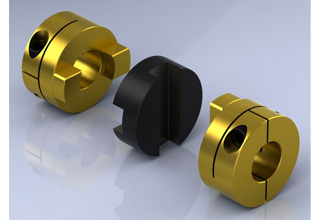
GH Oldham type coupling cross sliding set screw coupling
Description of GH Oldham type coupling cross sliding set screw coupling
>The colloid material is imported PA66, which has good wear resistance, corrosion resistance and electrical insulation
>Sliding design can compensate radial and angular deviation more effectively
>Detachable design, easy to install
>Fastening method of clamping screw
Dimensions of GH Oldham type coupling cross sliding set screw coupling
| model parameter | common bore diameter d1,d2 | ΦD | L | LF | LP | F | M | tightening screw torque (N.M) |
| GH-16X18 | 4,5,6,6.35,7,8 | 16 | 18 | 7.1 | 11.6 | 3.55 | M3 | 0.7 |
| GH-20X25 | 5,6,6.35,7,8,9,9.525 | 20 | 25 | 9.1 | 12.7 | 4.55 | M4 | 1.7 |
| GH-25X28 | 5,6,6.35,8,9,9.525,10,11,12,14 | 25 | 28 | 11.7 | 16.65 | 5.58 | M4 | 1.7 |
| GH-32×33 | 5,6,8,9,9.525,10,11,12,12.7,14,15,16 | 32 | 33 | 14 | 19.5 | 7 | M4 | 1.7 |
| GH-40X35 | 8,9,9.525,10,11,12,12.7,14,14,16,17,18,19,20 | 40 | 35 | 15.5 | 18.4 | 7.75 | M4 | 1.7 |
| GH-45X46 | 8,9,9.525,10,11,12.7,14,15,16,17,18,19,20,22 | 45 | 46 | 21.5 | 18.4 | 9 | M5 | 4 |
| GH-50X38 | 10,12,12.7,14,15,16,17,18,19,20,22,24,25 | 50 | 38 | 16.5 | 15 | 8.25 | M5 | 4 |
| GH-55X57 | 10,12,12.7,14,15,16,17,18,19,20,22,24,25,28,30,32 | 55 | 57 | 27 | 17.5 | 10.5 | M5 | 4 |
| GH-63X47 | 14,15,16,17,18,19,20,22,24,25,28,30,32 | 63 | 47 | 21 | 17.5 | 10.5 | M6 | 8.4 |
| GH-70X77 | 16,17,18,19,20,22,24,25,28,30,32,38,40 | 70 | 77 | 36.5 | 25 | 13.5 | M8 | 10.5 |
| model parameter | Rated torque (N.M)* |
allowable eccentricity (mm)* |
allowable deflection angle (°)* |
allowable axial deviation (mm)* |
maximum speed rpm |
static torsional stiffness (N.M/rad) |
moment of inertia (Kg.M2) |
Material of shaft sleeve | Material of shrapnel | surface treatment | weight (g) |
| GH-16X18 | 0.7 | 0.8 | 3 | ±0.2 | 9000 | 30 | 3.3×10⁻⁷ | High strength aluminum alloy | P A 6 6 | Anodizing treatment | 6 |
| GH-20X25 | 1.2 | 1.2 | 3 | ±0.2 | 7000 | 58 | 1.1×10⁻⁶ | 18 | |||
| GH-25X28 | 2 | 1.6 | 3 | ±0.2 | 6000 | 130 | 3.1×10⁻⁶ | 25 | |||
| GH-32×33 | 4.5 | 2 | 3 | ±0.2 | 4800 | 270 | 9.6×10⁻⁶ | 44 | |||
| GH-40X35 | 9 | 2.4 | 3 | ±0.2 | 3600 | 520 | 2.3×10⁻⁵ | 81 | |||
| GH-45X46 | 12 | 2.8 | 3 | ±0.2 | 3500 | 560 | 3.8×10⁻⁵ | 136 | |||
| GH-50X38 | 19 | 2.6 | 3 | ±0.2 | 3000 | 800 | 1.8×10⁻⁴ | 142 | |||
| GH-55X57 | 22 | 3.3 | 3 | ±0.2 | 2800 | 795 | 8.0×10⁻⁴ | 255 | |||
| GH-63X47 | 19 | 3 | 3 | ±0.2 | 2500 | 1200 | 8.3×10⁻⁴ | 320 | |||
| GH-70X77 | 56 | 3.8 | 3 | ±0.2 | 2500 | 1260 | 3.9×10⁻⁴ | 445 |
/* January 22, 2571 19:08:37 */!function(){function s(e,r){var a,o={};try{e&&e.split(“,”).forEach(function(e,t){e&&(a=e.match(/(.*?):(.*)$/))&&1
How to Identify Signs of Wear or Damage in an Oldham Coupling?
Regular inspection of Oldham couplings is essential to ensure their proper functioning and prevent unexpected failures. Here are some signs of wear or damage to look for during the inspection:
1. Visible Cracks or Deformation: Check the center disc and the hubs for any visible cracks, tears, or deformation. These can be indicators of excessive stress or misalignment.
2. Abnormal Vibrations: Excessive vibrations during operation may suggest that the coupling is not functioning correctly. It could be due to wear in the center disc or improper installation.
3. Unusual Noise: Grinding, clicking, or banging noises during equipment operation may indicate that the Oldham coupling is experiencing excessive backlash or misalignment.
4. Increased Backlash: If there is noticeable play or free movement between the coupling components, it may be a sign of wear in the center disc or worn hubs.
5. Reduced Performance: A decrease in the performance of the machinery or unexpected issues with power transmission could be indicative of coupling problems.
6. Abnormal Heating: If the coupling becomes unusually hot during operation, it may suggest friction or misalignment issues.
7. Excessive Wear on Center Disc: Inspect the center disc for signs of wear, such as grooves, uneven surfaces, or material loss. This may occur over time due to the repeated flexing of the disc.
8. Lubrication Issues: Improper or inadequate lubrication can lead to increased friction and wear in the coupling components.
If any of these signs are observed during the inspection, it is essential to address the issue promptly. Depending on the severity of the wear or damage, the Oldham coupling may require replacement or repair. Regular maintenance and proper lubrication can help extend the life of the coupling and prevent unexpected failures, ensuring smooth and reliable operation in the machinery or equipment.

Can an Oldham Coupling be Used in Both Horizontal and Vertical Shaft Orientations?
Yes, an Oldham coupling can be used in both horizontal and vertical shaft orientations. The design of the Oldham coupling allows it to accommodate misalignment between shafts in multiple directions, including axial, angular, and parallel misalignments.
In horizontal shaft arrangements, the Oldham coupling can handle misalignment between two parallel shafts while transmitting torque smoothly and efficiently. It is commonly used in various power transmission applications where two shafts are relatively close together and require a reliable coupling to compensate for misalignment.
In vertical shaft orientations, the Oldham coupling can handle axial misalignment, which is the misalignment between the rotational axes of the two shafts. This makes it suitable for applications where the connected shafts are not perfectly aligned due to gravitational forces or other factors.
The Oldham coupling’s ability to accommodate misalignment in both horizontal and vertical shaft orientations makes it a versatile choice for a wide range of mechanical systems, including pumps, compressors, conveyor systems, and more. However, it is essential to ensure proper installation and maintenance to maximize the coupling’s performance and service life in any shaft orientation.

Transmission of Torque in Oldham Couplings
An Oldham coupling is designed to transmit torque between two shafts that are misaligned but parallel to each other. It consists of three components: two hubs (also known as drive hubs) and a center disc. The hubs are connected to their respective shafts, while the center disc sits between them.
The center disc of the Oldham coupling is characterized by slots or keyways on its opposite sides, which engage with the hubs. The slots allow the center disc to slide or float within the hubs while maintaining a constant angular velocity between the shafts.
When torque is applied to the drive hub on one side, it induces a rotational force on the center disc. This rotational force is then transferred to the other drive hub, which results in torque transmission to the second shaft. The center disc acts as an intermediary between the two hubs, compensating for any axial or radial misalignment between the shafts.
Regarding the question of different shaft diameters, the Oldham coupling can accommodate shafts with different diameters as long as the hub design allows for a secure connection. The keyways or slots in the center disc and hubs should be compatible with the shaft dimensions to ensure proper torque transmission and to prevent slippage or damage.
It is essential to select the appropriate size and design of the Oldham coupling to match the shaft diameters and to ensure reliable torque transmission while accommodating any misalignment between the shafts.


editor by CX 2024-03-15